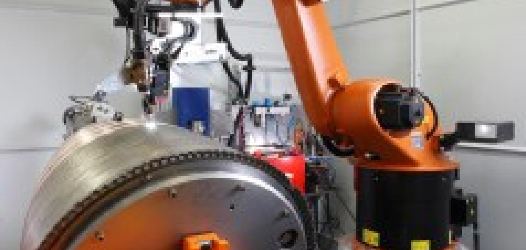
An automated welding system employing structured lighting and machine vision has been used to weld the upper stage nozzle of the Ariane 5 rocket, which made its 50th flight from the Kourou spaceport in French Guiana on 21 May 2010.
Supplied by Oxfordshire manufacturer, Meta Vision Systems, the laser-based tracking system, Meta Scout, is able to detect and follow a joint even when there is no discernable gap or step.
Before welding, the nozzle profile is created by bundling the tubes together and spiral winding them around a copper-coated aluminium mandrel. The tubes are held together with binding wire, which is unwound step by step as welding proceeds. Total welded seam length in each nozzle is approximately 730m.
The width of each tube varies slightly along its length to optimise coolant flow and enable uniform heat distribution. During a majority of the welding process, which does not use any filler material and therefore does not add weight to the nozzle, the Meta-Scout is able to resolve the seam between adjacent tubes and follow it conventionally. However, the square profile of the tubes near the engine end is flattened to achieve the correct fit, with the result that there is no visible feature to track.
It is here that the sensor uses its novel 'zero gap' functionality to direct the robotically-deployed torch to weld the joints. Five laser lines projected onto the workpiece surface allow measurements in six degrees of freedom, three orthogonal and three rotational.
A structured light technique together with grey level vision analysis determines seam position, height and orientation with respect to the tool, despite the absence of a physical feature. The only provisos are that the material either side of the gap must have similar machined finishes and the sensor has to be positioned at close to 90° to the surface.
Advanced planning software allows the non-linear path to be predicted and followed to an accuracy of 0.1mm. The robot is guided in real time, without the need to carry out a laborious teach-in process. Only the start of the joint and the search direction need to be entered.
Weld parameters are automatically selected to suit the measured gap dimensions. A calibration system aligns the sensor with the welding torch and calculates any deviation of the TCP (tool centre point), which is automatically corrected by the robot controller. The automated welding process can be monitored on a screen located outside the enclosed cell in which the equipment is installed.