How do you choose a 3D vision system for a robot cell? Geraldine Cheok and Kamel Saidi at the National Institute of Standards and Technology in the USA discuss an initiative to define standards for industrial 3D imaging
Robots have been assembling parts into products since the mid-20th century, often relying on jigs and fixtures to position parts in exact locations. A key element to further automating the robotic assembly process is the availability of three-dimensional information about the parts and the robot’s surroundings.
For robots to be able to perform tasks, they have to be able to perceive their environment. Perception is seeing (sensing) and understanding (interpreting). Sensing employs various measurement techniques such as stereo vision, structured light, and time-of-flight (ToF), while interpreting involves data analysis.
In manufacturing, 3D imaging systems are now often used to determine the pose, or position and orientation, of an object; to identify a part; for collision avoidance and safe human-machine collaboration; as well as inspection and quality control. But determining the suitability of a system depends on the particular application – the part to be located or measured, for example – as the requirements differ in terms of accuracy, range or work volume, resolution, acquisition and processing time, environmental conditions, ease of use (such as the amount of training required), system weight and size, and cost.
The need for standards
Currently, users must rely on manufacturer specifications when trying to make informed decisions as to which 3D imaging system best suits their needs. However, reliance on manufacturers’ specifications presents two primary challenges for users. First, there is little common terminology. For example, the term resolution can mean spatial resolution, image resolution, depth resolution, smallest feature discernible, smallest change in lateral distance or depth that is detectable, or angular resolution, among others.
Another commonly used term is accuracy, which is often misused to mean error, uncertainty, or repeatability. (It should be noted that accuracy is a qualitative concept and not a quantitative one.) Another term is measurement noise, which is sometimes used to mean one standard deviation of multiple measurements, but how many measurements? Also, is it two or three standard deviations? Or is it the root mean square (RMS) of the fit of a geometrical entity such as a plane or sphere?
Without common terminology, comparisons between systems are not possible, and it makes understanding a system’s capabilities or limitations very difficult.
The second challenge is the lack of standard test methods. Let’s say that specifications for position uncertainty are given by the manufacturers and the term is properly defined. The problem, then, is that these specifications may have been obtained based on different test methods and test conditions. One method may have used spherical targets with 90 per cent reflectivity, fluorescent lighting, and required only one measurement; while another may have used planar targets with 50 per cent reflectivity, LED lighting, and multiple measurements. These differences may seem subtle, but they will impact the measurements and reported results. Without a standard test method, a reasonable comparison is not possible.
Additionally, standards are beneficial to both users and manufacturers. Standard test methods allow manufacturers to determine specifications for their system and users to verify a system’s specifications under ideal or real-world conditions. Standards that are developed for system verification may also be used to determine when a system needs to be recalibrated, or interim standard tests may be specifically developed for this purpose.
As mentioned earlier, standardisation of test procedures and conditions is required for system comparisons. However, in some cases, users need to know how their system would perform under slightly different conditions – conditions applicable to their particular application. A standard test method allows the user to characterise their system by performing the test procedure for the changed condition. For example, if a test method specifies LED lighting, the user may still perform the test, adhering to all specified procedures, but change the lighting to fluorescent to match the lighting condition that exists for their application. Similarly, reflectance other than that specified in a test method may be used to evaluate a system’s performance for different reflectances. In brief, a basic standard test method allows users to extend it for other conditions encountered in the real world and that cannot be covered by a standardised test method.
Based on the measurement technology, a standard test method developed for one type of system may not necessarily be applicable to another type of system. This is because the sources of measurement error are different for different measurement technologies, and the test procedures to reveal the underlying errors for one type of technology may not reveal the underlying errors for another type of technology. Often, users are not aware of the factors affecting the performance of a system and may not be aware that a test method may be biased against one type of measurement technique. Standards, therefore, allow a fair playing field for both users and manufacturers.
Existing standards
Anyone who has been involved in the development of standards can attest to the fact that it can be a long process. As alluded to previously, considerable expertise and research is required to determine relevant or contributing factors to the performance of a 3D imaging system. Care must be taken to ensure test methods are not biased towards or against any system and do not exclude any system.
Another challenge when developing a standard is the need to balance the cost involved in performing the test – the equipment required such as a laser tracker or specialised artefacts, for instance – and the time needed to conduct the test, with the need to develop a test method that is meaningful. And finally, consensus must be reached to ensure confidence and acceptance of the standard.
Of the machine vision standards that currently exist, only two are relevant to the performance evaluation of 3D imaging systems for robotic assembly applications. The VDI/VDE 2634, Part 2 and Part 3, covering optical 3D measuring systems – Part 2 looks at optical systems based on area scanning, while Part 3 addresses multiple view systems – evaluate the ‘sphere spacing error’ and ‘flatness measurement error,’ among other metrics. The ASTM E2919 standard test method specifies a procedure for calculating a 3D imaging system’s error in measuring the pose of a single, static object.
Four other standards could also be relevant. ASTM E3064 evaluates the relative pose error in measuring the pose of a moving, rigid object, while ASTM E3124 evaluates the latency in a system’s measurement. Both of these standards were developed for optical tracking systems, but the same procedures could be used for other 3D imaging systems if apparatuses that do not require markers are used.
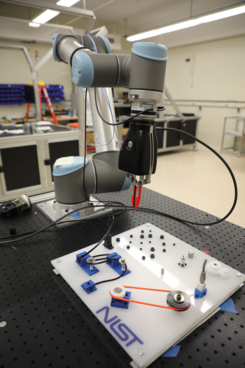
A robot arm with 3D perception inside the gripper grasping an object. Credit: NIST
The other two standards are intended for longer range, terrestrial laser scanners: ASTM E2938 evaluates the relative-range measurement performance of 3D imaging systems, and ASTM E3125 looks at the point-to-point distance measurement performance of spherical coordinate 3D imaging systems. The test methods specified in these two standards could be modified for 3D imaging systems used in robotic assembly applications.
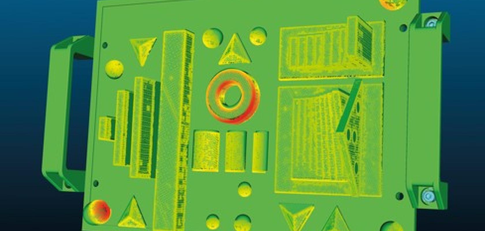
There are also two reference artefacts that were developed by the National Research Council of Canada [1] and the National Physical Laboratory in the United Kingdom [2], respectively, that may be relevant. The use of reference artefacts allows for easy comparisons between systems.
Measuring performance
The National Institute of Standards and Technology (NIST) is working with the 3D imaging industry to develop performance standards for systems that can be used for robotic assembly applications. These standards are being developed through the ASTM Committee E57 on 3D Imaging Systems (ASTM E57).
NIST and ASTM E57 held a series of virtual meetings with 3D imaging stakeholders in 2019 to develop a list of the standards that are needed. These meetings culminated in a two-day workshop that was held at NIST in December 2019 [3] in which a list of needed standards was refined and prioritised.
A roadmap of the standards needed for 3D imaging systems that can be used for robotic assembly applications is under preparation.
Of the 39 standards identified, the participants chose the six highest-priority standards and expanded them into work items for immediate development. These standards are:
1. Best practice for considering the effects of lighting on the output of a 3D imaging system;
2. Test method for evaluating the performance of a 3D imaging system across the specified field of view (FOV);
3. Test method for verification of a 3D imaging system’s specified FOV;
4. Standard reference artefact(s) to evaluate the performance of a 3D imaging system;
5. Terminology for describing the time delay in 3D image sensor output;
6. Test methods for determination of a 3D perception system’s point-wise spatial resolution.
As a result of the workshop, two ASTM task groups formed in April and May 2020, and are working on items two and six from the above list. A third task group will work on item five and will be convened soon. The remaining three items will either be incorporated into items two and six or will be tabled until the three task groups (items two, five and six) have been completed.
Members of these task groups represent various interests and several major sensor manufacturers are represented. The time frame to publishing these standards will depend on the level of participation and commitment of the task group members. Users of 3D imaging systems can also drive the development process by asking for standards and participating in their development.
Participation from users and producers of 3D imaging systems in the development of these standards is encouraged. Please contact the authors for more information about how to get involved.
The authors
Geraldine Cheok is a research structural engineer, and Dr Kamel Saidi is a mechanical engineer, both in the Intelligent Systems Division of the National Institute of Standards and Technology: cheok@nist.gov; kamel.saidi@nist.gov.
Certain entities are mentioned in the text. In no case does such an identification imply recommendation or endorsement by the National Institute of Standards and Technology, nor does it imply that the products are necessarily the best available for the purpose.
References
1. Carrier, B., MacKinnon, D. K., and Cournoyer, L., Performance evaluation of 3D imaging systems based on GD&T, Manufacturing Letters, 1, 1, https://doi.org/10.1016/j.mfglet.2013.08.004, September 2013.
2. McCarthy, M. B., Brown, S. B., Evenden, A., and Robinson, A. D., NPL freeform artefact for verification of non-contact measuring systems, Proceedings of SPIE - The International Society for Optical Engineering, January 2011.
3. Saidi, K., Cheok, G, Qiao, H., Horst, J., Franaszek, M., Proceedings of the ASTM E57 workshop on standards for 3D perception systems for robotic assembly applications 2-3 December 2019, https://doi.org/10.6028/NIST.AMS.100-33, Gaithersburg, MD, April 2020.
---
Latest commercial products
Among the 3D vision products released recently include Matrox Imaging’s AltiZ 3D profile sensors, Lucid Vision Labs’ Helios2 time-of-flight camera that has just entered series production, and industrial-grade versions of Intel RealSense cameras from Framos.
The Matrox AltiZ dual-camera, single-laser profile sensor (see featured product below) is designed to reduce occlusions in a 3D scan. It offers more robust 3D image reproductions than would normally be achievable with single-camera models, according to Pierantonio Boriero, director of product management at Matrox Imaging. When working with single-camera models, occlusions can be dealt with by adding another sensor, although this adds to the cost of the system.
Matrox AltiZ cameras can work in either synchronised or alternate fashion, the former mode providing excellent 3D reproduction, while the latter delivers a higher scanning rate (up to 4,874 profiles per second in alternating acquisition mode with 64 sensor lines; at 1,280 sensor lines the rate is 336 profiles per second in alternate mode, or 168 profiles per second in synchronous acquisition mode; the sensor has 1,984 points per profile).
AltiZ analyses the laser beam line of both cameras within its embedded computer, giving greater control over spurious data.
‘Cost and complexity of currently available solutions are quite possibly the two most important factors holding back the use of 3D vision in industrial inspection,’ commented Boriero, speaking to Imaging and Machine Vision Europe. ‘Some key design goals with the Matrox AltiZ were to design an affordable solution without compromising performance, assure ease of use, and minimise complexity in deployment.’
Lucid Vision Labs’ Helios2 time-of-flight camera offers 3D depth data with sub-millimetre precision at one metre distance. The camera is based on Sony’s DepthSense IMX556PLR back-illuminated ToF image sensor, and uses four 850nm VCSEL laser diodes. It delivers 640 x 480-pixel depth resolution at up to an 8.3-metre working distance, and at a frame rate of 30fps.
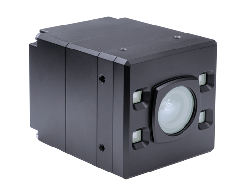
Helios2 ToF camera
Additional features include six different operating distance modes, an integrated ambient light filter, a wider field of view, multi-camera support, and a flying pixels filter. The camera is available with an IP67-rated enclosure with lens protection, GigE Vision PoE, and industrial M12 connector for up to 100-metre cable length.
Framos’ industrial stereoscopic depth camera, D415e, is built with Intel’s D410 depth module and Intel’s D4 vision processor. The camera has an industrial enclosure equipped with lockable connectors for gigabit Ethernet (M12), power supply, and GPIO (M8). It can also be configured to run using power-over-Ethernet.
The D415e camera has a field of view of 72° diagonal, a minimum z-distance of 0.16m, and uses rolling shutter sensors. The camera’s sister, the D435e, which is based on a global shutter sensor, will be available in the autumn of 2020. In addition, Framos has designed its own processing board to meet industrial interface requirements.
On the software side, Euresys has introduced its Easy3D library, which provides functions to generate ZMaps to deal with 2.5D data. A ZMap is the projection of a point cloud on a reference plane, where distances are stored as pixel greyscale values. ZMaps are distortion free, with a metric coordinate system.
Easy3D has functions to convert arbitrary 3D data, such as point clouds, to 2D representations, which form the ZMaps. ZMap data are calibrated, so distances, heights and angles can be measured in metric units, or pixels. Each value of a ZMap represents the distance from a 3D point to a reference plane. By using ZMaps with well-known and fast 2D operators, the user has access to an effective 2.5D processing pipeline.
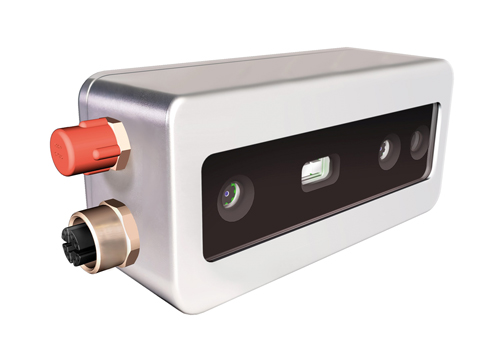
Framos’ stereoscopic depth camera, D415e
Other new technology that is now on the market includes that from Montreal startup, Airy3D, which was founded in 2015. The company’s DepthIQ is a 3D computer vision platform that can convert any camera sensor into a 3D sensor, for generating both 2D images and depth maps that are inherently correlated.
DepthIQ uses a transmissive diffraction mask to encode the phase and direction of light into the pixel intensity, generating a dataset of integrated, innately registered, 2D image and depth data. The transmissive diffraction mask can be applied over any CMOS sensor, while an image depth processing software block decodes the image. The product’s compressed dataset offers savings in hardware, size, and computational load, enabling faster, cheaper, and smaller 3D solutions.
Airy3D says DepthIQ is a low-cost alternative to complex and costly 3D technologies such as time-of-flight, stereo, or structured light in existing near-field 3D applications, or where 3D doesn’t exist. Moreover, it can also enhance these other 3D technologies in wide-field applications by replacing the RGB sensors with DepthIQ-powered sensors to improve close depth and extend far depth, increase depth accuracies, fill in occlusion zones, simplify computation, and monitor drift.
Also new on the market is technology from HD Vision Systems, which was founded in 2017 and is now conducting a number of successful pilot projects with its Lumiscan camera. LumiscanX computes a 3D image from 13 discrete 1.2-megapixel cameras built into one housing. The camera has been designed for robotics, automation and quality inspection.
---
Smart Vision Lights, featured product
Smart Vision Lights’ LED Light Manager (LLM) addresses lighting control needs of multi-light machine vision solutions, including photometric 3D, multispectral, and other multi-light or large-area inspection systems. The LLM drives up to four separate lights of virtually any type or up to four individual quadrants or channels within an integrated photometric or multispectral ring light solution. The LLM can manage multiple lights operating in continuous, Multi-DriveTM, or OverDriveTM strobe modes.
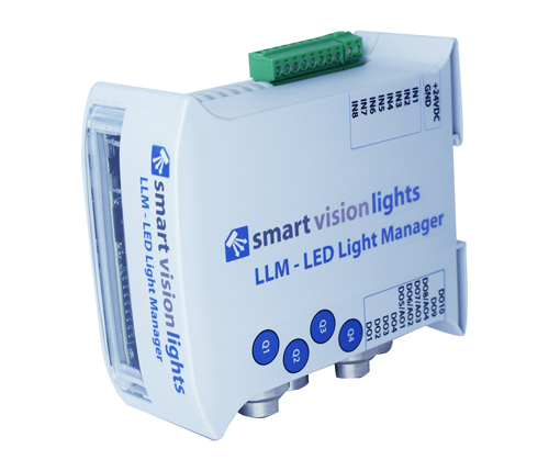
By capturing successive images of a stationary object as it is illuminated by a sequence of lights, photometric image processing software can determine the 3D surface orientation of every pixel across the object’s surface. The same technique can generate 2D images of multiple regions of interest using separate lights and/or cameras. LLM’s intuitive browser-based user interface makes it possible for technicians of any skill level to set image sequences and program intensities for each light.
https://smartvisionlights.com/products/llm
---
Matrox Imaging, featured product
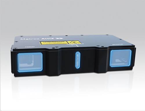
Award-winning Matrox AltiZ 3D profile sensors feature a unique dual-camera single-laser design that delivers exceptional 3D reproduction fidelity. Effectively combatting occlusions, these integrated high-fidelity sensors provide far more robust reproductions than achievable with single-camera models. An embedded vision algorithm analyses the dual-camera laser beam lines to establish dimensional measurements in real-world units, automatically generating various type of reliable 3D data as either individual profiles, depth maps, or point clouds. Specifically designed for inspection, measurement, and guidance tasks, this series of 3D profile sensors is ideally suited for automotive manufacturing, electronics production, lumber inspection, food and beverage production and packaging, logistics and warehousing, consumer goods inspection, medical device manufacturing, and pharmaceutical production sectors. Matrox AltiZ sensors implement a standard GigE Vision interface with GenICam extensions—GenDC, PFNC, and SNFC—for tremendous interoperability with a range of Matrox Imaging- and third-party machine vision software and controllers.