How do users choose the best lens for an imaging system? The answer is Modulation Transfer Functions, Edmund Optics’ Dr Boris Lange explained in our latest webcast
Ten or 15 years ago, when VGA sensors were considered high-quality and pixels were 10µm, it was pixel size that limited the performance of an imaging system. Today, with smaller pixels, it’s optics that can limit resolution.
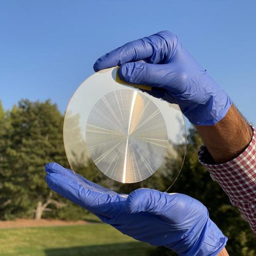
Edmund Optics offers 11 different 25mm C-mount lenses as standard products, along with additional custom lenses. This is because of the progress made in sensor technology; one standard lens is not enough to cover the range of image sensors available. So, how do users choose the best lens for a certain application? The answer is to use Modulation Transfer Function (MTF) curves, which are a good comparison tool – they give a measure with which to compare a €50 lens with a €150 lens or a €1,000 lens.
An MTF curve plots contrast along the y-axis and resolution in line pairs per millimetre along the x-axis. All MTF curves start in the upper left corner of the graph at 100 per cent contrast (0lp/mm equates to two objects that are infinitely far away and will always have 100 per cent contrast) and, as objects are brought closer together, the contrast drops.
Multiple curves are required to get a representative plot of how a lens will perform over the entire sensor – in the middle and at the edges – and at tangential and sagittal focus. The curves can also say how the lens will perform at a certain working distance, at the F#, and at the wavelength of light used.
Parameters for imaging performance
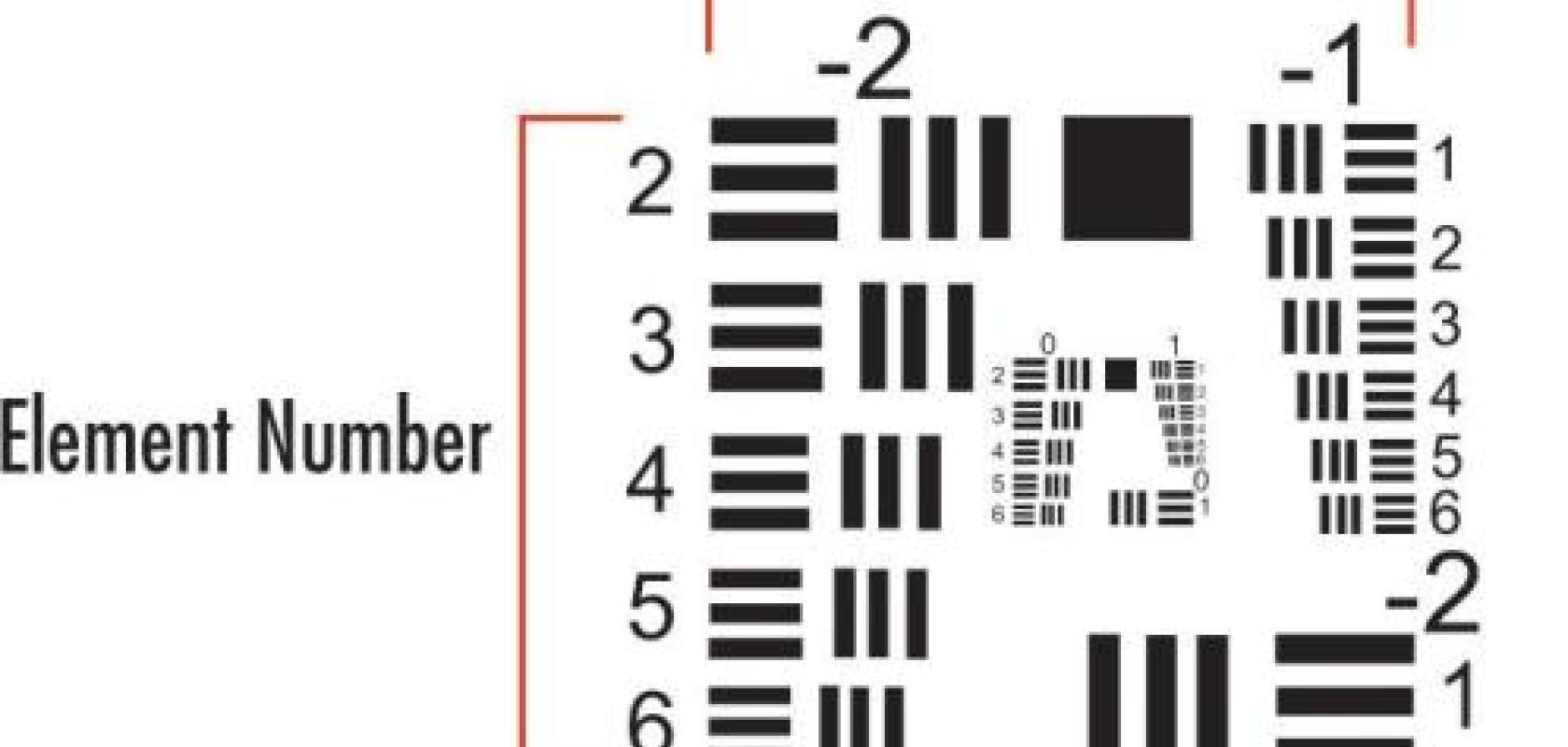
Contrast is an important metric for image quality. Contrast by itself, however, is useless if a spatial metric is not specified alongside it. Two objects through a lens will still have high contrast when the objects are far apart, but when the objects are moved closer together, at some point every optical system will have trouble resolving the detail and the two objects will eventually blur. The spatial metric tells the user how far away two objects are from each other – this is what optical engineers call resolution.
The resolution of a camera can be expressed in megapixels. But the resolution of an imaging system or the resolution of the optics is always a spatial metric, which is usually specified in micrometres or the distance apart of critical features. Optical designers might also use the inverse of micrometres which is line pairs per millimetre (lp/mm): 145lp/mm equates to a pixel size of 3.45µm; 100lp/mm would correspond to a 5µm pixel.
Another consideration the user must make is the position on the sensor where contrast and resolution are measured – the centre of the image or at the edges. The user can alter the focus to sacrifice performance in the middle of the image in order to gain performance at the edge.
In addition, resolution charts will specify a tangential and sagittal focus. Wavelength and the F# of the lens will also influence performance of the imaging system.
Advice for using MTF
MTF curves are not set in stone. Just as the user can focus a real lens, this can also be done in the optical design software. So, in design software, the user can sacrifice performance in the middle of the image for performance at the edge.
In addition, MTF curves don’t include manufacturing tolerances, so make sure there’s enough buffer between what you want and what is seen in the MTF curves. This might be a 10 or 15 per cent MTF point drop, going from nominal design in the perfect world to the real world.
Keep in mind specific application parameters when using MTF curves. Contrast will change depending on the working distance – you can get 30 per cent contrast at infinity, but 10 per cent contrast at a working distance of 75mm at 230lp/mm. The same is true with F#.
The best way is to think about the application: specify the contrast and the resolution needed for the feature size extracted in the centre or edge of the image, and then relate that to the MTF performance.
This information was taken from Dr Boris Lange’s presentation given for an Imaging and Machine Vision Europe webcast. Lange is manager imaging Europe at Edmund Optics. The company provides an Introduction to Modulation Transfer Function on its website.
Write for us
Want to write about the optical design of an imaging system you've developed and deployed? Please get in touch: greg.blackman@europascience.com.