Robots are designed for tasks that humans wouldn’t want to do or physically can’t do. Lifting and carrying, repetitive work, sorting, precision work – a robot’s job is to carry out a task over and over again with the same degree of accuracy so that the end result is a near-identical product to the one that went before it. In automating an industrial process, companies are looking to increase the turnover and the quality of what they manufacture.
Machine vision systems are the eyes of a robot. Markus Maurer, product manager of 3D technology at Vitronic, a German company specialising in industrial image processing, says: ‘Robots are programmed for specific tasks and are employed to automate a production process. By adding vision to robotics, the opportunity arises to add a control and feedback aspect to that process.’ He continues: ‘The combination of vision and robotics has the potential for improving automated production processes as well as for implementing robotic systems in areas that, in the past, were not considered automatable.’
Vitronic has developed VIROwsi, a 3D robotic inspection unit dedicated to the inspection of weld seams in the automotive industry. The robotic system uses a vision sensor to scan a laser line falling across the weld seam to check for defects in properties such as shape and porosity of the seam, as well as any gaps in the weld.
Vitronic’s systems are also suitable for the identification of complex and changing parts, such as the loading and unloading of hardening grids in the manufacture of gearboxes. ‘The 3D technology allows the robot to handle objects of various sizes, weights and surface conditions, as they move down a conveyor belt. Even if the dimensions of the part have changed due to wear, the sensor will identify the shape of the object and ensure the robot handles it accordingly,’ says Maurer.
A further advantage to the 3D method of inspection is that the system is unaffected by external lighting conditions, as the sensor is simply scanning the laser line.
Therefore any changes in lighting – if a shadow fell across the seam, for instance – would not have any influence on the inspection process.
‘When designing a robotic inspection system, the operational environment has to be taken into consideration,’ states Maurer. ‘In the case of an automotive factory floor, the system is exposed to electromagnetic fields and the components used must be able to withstand this.’
He goes on to explain that fibre optic cabling was utilised, as it is not affected by electromagnetic forces. However, the movement of the robotic arm often twisted cabling, causing standard cables to break; tougher versions were then required for the system.

The EDAG Best-Fit system, using digital cameras from Allied Vision Technologies, is designed to take into account geometric variations in vehicle doors and automatically calculate the best possible fit during assembly. Image courtesy of Allied Vision Technologies.
VIROwsi is a post-production inspection system, designed to ensure each welded seam is of a high quality. German company EDAG, a provider of customised solutions for the automotive industry, has developed a Best-Fit robotic system to optimise the assembly of car body parts, (mainly doors). The system utilised digital cameras supplied by Allied Vision Technologies (AVT), a company with headquarters in Stadtroda, Germany, manufacturing cameras and components for industrial image processing.
In automotive manufacturing, the geometry of stamped parts, such as car doors, can vary slightly within production tolerances. That means that each car body and each door can have slightly different dimensions, which becomes apparent in the gap generated when the parts are assembled.
‘Automakers want to reduce the gap to a minimum and at least ensure a regular, parallel gap and an optimal flush between the door and the car body,’ explains Horst Mattfeldt, technical director at AVT. ‘The purpose of EDAG Best-Fit is to adapt the fitting position of both parts to their actual geometry in order to achieve the best possible fit for each individual car and each individual door, in spite of varying dimensions from car to car and from door to door.’
A vision sensor is mounted at several critical points on the robot arm that measures the gap and flush between both parts. The data is then analysed by software that calculates the optimal fitting position and transmits it to the robot. ‘Vision makes it possible to switch from a standard fitting position, based on a theoretical size of the parts, to a fitting position adapted to the actual variations within inevitable tolerances,’ says Mattfeldt.
Before the Best-Fit system was introduced, car bodies were assembled by robots using mechanical gauges assuming that all bodies and all doors had the same specified dimensions, which is not always the case due to production tolerances. Substantial manual re-adjustment sometimes had to be carried out to achieve the requested fitting quality – but this is costintensive and does not guarantee the highest quality standard across the line. With the EDAG Best-Fit system, the assembly robot takes into account the reality of geometry variations and automatically calculates the best possible fit for each individual car.
‘The system can be programmed according to different fitting strategies, depending on the different quality standards of different brands or vehicle types,’ says Mattfeldt. ‘For example, one strategy can be to trade off gap width in the lower, less visible part of the car for a better fit in more visible areas.’
The system is also able to learn from previous experiences. For instance, because of its own weight, the door might hang a little deeper than calculated. The system checks if the outcome meets the expected result and this is taken into account in the calculations of the next vehicle to be assembled, thereby optimising the best-fit position over time.
Robotic systems can also be programmed to sort items of different sizes and shapes, using machine vision to distinguish between them. IPL Transmission, part of the Danish company IPL Group and a manufacturer of transmission elements and machine parts, has implemented a ‘bin pick’ robotic system, based on a robot from US company Motoman and the IVC3D camera from Sick IVP.
The system is set up to automate the manufacture of camwheels – a toothed wheel composed of three metal pieces and used as a component part of motors. The three metal pieces are fitted together in a hydraulic press, an assembly process that was, in the past, carried out manually.
‘An IVC3D camera positioned over a pallet of component parts, varying in size from 30mm to 200mm, relays coordinates of individual parts to a robot, which picks out the correct components to make a complete camwheel,’ explains John Grøndahl, product specialist at the Danish branch of Sick IVP, a Swedish supplier of 3D machine vision systems and part of the Sick Group.

An IVC3D camera positioned over a pallet of component camwheel parts guides a robot to pick out the correct components to assemble a complete camwheel. Image courtesy of Sick IVP.
The system not only has to contend with different sized parts, but also has to ensure each part is in the correct orientation for assembly, as the metal pieces are not identical on both sides. Component parts also vary in colour, from shiny metallic to matt black, which a 2D camera would find difficult to distinguish between. ‘Sick’s 3D camera generates a profile of the part, which negates any confusion caused by colour and also makes orientating the part for assembly easy to achieve,’ says Grøndahl.
Producing a complete 3D image of each piece enables an operator to view the part clearly and identify the reason for any failures in production. The XYZ coordinates from the 3D profile are used to control the robot directly, rather than integrating the coordinate system of the camera into a different coordinate system used by the robot.
‘This is a classic “bin pick” automated system, with robots sorting and matching up a wide variety of component parts,’ explains Grøndahl.
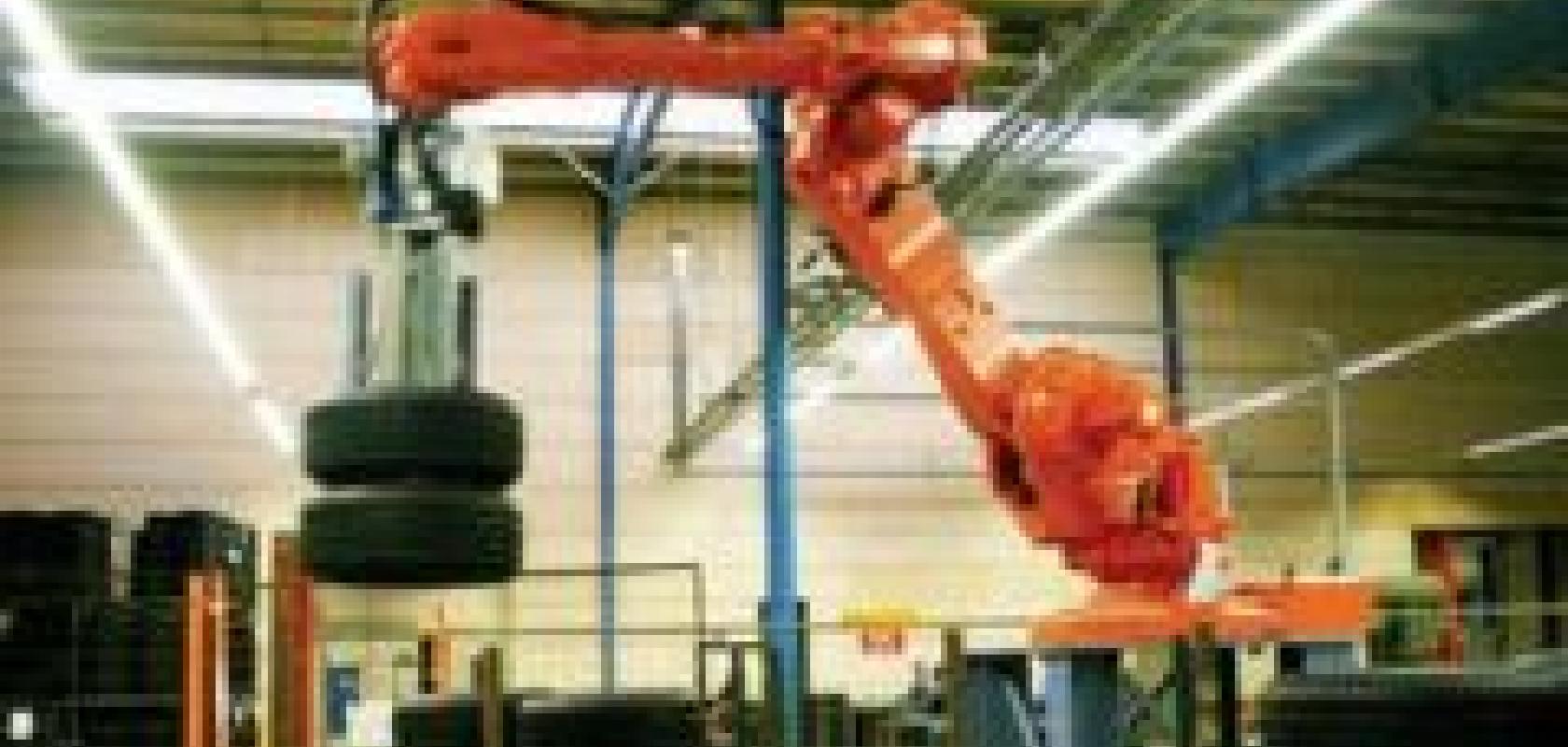
The 3D technology provides a big advantage over 2D vision systems for this kind of application and, with a reduction in the price of 3D machine vision, Grøndahl expects to see a growth of 200-300 per cent in the next one to two years for robotic systems using 3D vision technology. In the automotive industry robots are often employed to carry out manual labour, such as lifting heavy parts. The Dutch company Sedeco Vision Components and M8, also Dutch and a manufacturer of OEM machine vision technology, have developed a machine vision unit for automated handling of vehicle tyres. The system, which is attached to a robotic arm, consists of a VC4038 smart camera from German company Vision Components, supplied through Sedeco, four M8 line lasers and some custom-developed hardware.
The robot arm with a gripper attached is inserted into the centre of a pile of tyres, which are stacked together on pallets. The gripper then grabs the tyres by expanding, allowing the robot to move the tyres onto a conveyor belt. Laser lights on the robotic arm project crosshairs onto the tyre pile, which enables the smart camera to calculate the centre point of the stack and the gripper to be positioned correctly.
‘The tyre stacks are not exactly vertical and the compact vision system must find the centre of the pile to ensure a correct pick and that tyres are not damaged by the robot,’ explains Servaes Joordens, owner of M8. ‘Imaging black tyres on a black background is a challenge for vision systems, but projecting laser lines onto the tyres allows the smart camera to find the centre of the pile with relative ease and provides the robotic arm with the correct “pick-up coordinates”.’

The VIROwsi from Vitronic, a 3D robotic inspection unit dedicated to the inspection of weld seams in the automotive industry. Image courtesy of Vitronic.
Allied Vision Technologies’ Mattfeldt explains that, thanks to digital imaging, it has become easier to make vision systems communicate with automated systems. ‘Typically, vision systems used to be implemented to check the quality of finished goods or parts on the production line and sort out defects. Now, the measured data can be quickly and directly fed into automated systems upstream for correction. The next step is to implement vision systems in direct combination with the robotic system, as demonstrated by the EDAG Best-Fit system. In this way, vision is no longer used for post-production inspection, but rather to optimise assembly quality in the first place.’
Mark Williamson, sales and marketing director at Firstsight Vision, a UK-based provider of vision technology and part of the Stemmer Imaging Group, says: ‘The amount of individual parts involved in connecting a camera to a robot is gradually reducing. The traditional method for connecting a vision system to a robot involved four components: a dumb camera would feed into a vision processor box which would link in with a robot controller box that would guide the robot. This was reduced to three components with the advent of smart cameras, which combined camera and vision processor.
‘The people responsible for programming robots didn’t understand vision and vice versa, so there was often a programming barrier involved in integrating the two systems,’ he adds.
Stemmer Imaging, Firstsight Vision’s parent company, has developed a product based on its Common Vision Blox software, which is installed directly on the robot controller and is controlled via the robot’s programming language. Using the module, dubbed V4R (Vision for Robots), an industrial camera can be fully integrated into a robotic system using only one set of programming languages. ‘The camera is connected directly to the robot controller via a Gigabit Ethernet interface and the software runs the vision system on the robot. V4R, therefore, cuts out processor intermediaries by allowing the vision unit and robot to talk directly to each other,’ says Williamson.
‘Robots are traditionally programmed to move between set positions,’ he explains. ‘Typically robots can be used to make inspections at certain coordinates and move between these coordinates in a fixed pattern. This is a very simple way of using robotics and machine vision. When vision starts to control a robot intelligently, as opposed to just positioning the inspection view, then this becomes a much more useful tool. For instance, sorting applications, where multiple items pass down a conveyor belt in random positions and are automatically sorted by the robotic system, make good use of this technology.’