Researchers at the AIT Austrian Institute of Technology are seeing increase demand from industry for imaging technology that can deliver both 2D and 3D capabilities in one platform. It is for this reason that over the past five years the institute has been developing inline computational imaging.
Computational imaging is itself a fast-growing research field in which new image acquisition technologies are being combined with intelligent algorithms. By doing this, image information can be extracted, which conventional machine vision can’t usually capture.
Two prominent examples of computational imaging are photometric stereo and light field. Photometric stereo involves multiple images of a stationary object taken by a single camera with a fixed point of view. In each image, the scene is illuminated from a different angle. Light field imaging, on the other hand, consists of multiple images of an object taken from different viewing angles, which is often achieved using either multiple cameras, or by putting a microlens array between the lens and image sensor. Combining these multiple views with advanced algorithms gives more accurate and robust depth information.
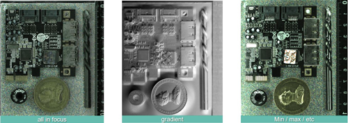
Inline computational imaging uses a single area scan camera that captures several views of an illuminated moving object simultaneously by exploiting the relative motion between the object and camera. A number of images are taken, with the light coming from a different direction in each, resulting in a stack of images containing varying light field data. High-performance computational processing of this data then makes it possible to derive depth information and obtain an all-in-focus image with increased signal-to-noise ratio. This approach also captures photometric stereo data as the illumination angle varies, thanks to the relative movement between illumination and object. By analysing the reflectance properties, the slope of the object’s surface – as well as information about the material – can be obtained. The result is a full 3D reconstruction of the object as a point cloud, as well as enhanced, rectified 2D images of the object.
‘By simultaneously acquiring light field and photometric information, this approach provides a simple, scalable framework for simultaneous, high-speed 2D and 3D inline inspection,’ explains Petra Thanner, a senior research engineer for high-performance vision systems at the AIT’s Center for Vision, Automation and Control.
‘This enables a whole manner of both 2D and 3D inspection tasks to be performed together with a single camera, sensor and lens – that’s a really high benefit,’ Thanner adds. She says that integration, setup and maintenance is a lot simpler compared to other solutions using an array of cameras, such as light field imaging.
An additional advantage over photometric solutions is that, conventionally, the object has to be stopped underneath a central camera within a bulky light dome consisting of several illumination sources, each of which needs to be activated individually in a sequence as the images are captured. Inline computational imaging differs from this, as it uses four LED lights strobed at high frequency, which allows images to be captured as the object moves under the camera.
Tilting a circuit board
Asked what the motivation for the AIT developing such a solution was, Thanner explains: ‘There are lots and lots of requests from industry for this technology, as there’s an increasing number of requirements or tasks that can’t be solved by 2D or 3D alone, but instead needs a combination – for example, PCB inspection.
‘So, on a PCB there are printed wires, labelling and a number of soldered components that all need inspecting to make sure they are parallel to the PCB, rather than being tilted in an undesirable way. Inline computational imaging… can mimic what a human is doing when inspecting a challenging surface. A human tilts and varies their viewing angle to inspect a surface, with different perspectives and illumination directions. While traditionally machine vision solutions have not been able to solve this task, with inline computational imaging, machine vision can now mimic this human behaviour.’
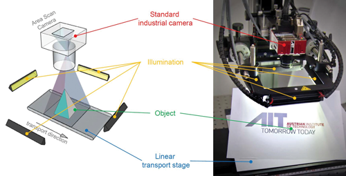
The components of an inline computational imaging setup. Credit: AIT
In addition to PCBs, the technique is suited to inspecting challenging surfaces such as metals, or those where there is a combination of printed and metallic surfaces.
‘You can use it on metallic surfaces to detect cracks,’ Thanner continues. ‘We have also used it to measure connectors, or dark chip sockets with a huge number of tiny metallic pins. Using inline computational imaging enables the socket to be measured to see if there is a label on it, read what’s printed on the label, and also to reconstruct the pins and measure the height of each of these pins.’
Dealing with data
The system does produce a lot of data and therefore requires a fast processor. Thanner explains: ‘As we are over-sampling the scene to capture the different viewing and illumination angles, you have to deal with a much higher data volume than you would have with traditional 2D or 3D imaging cameras, or solutions where only one image is captured before processing takes place. Instead we capture images while an object moves beneath the camera and then we process all that data together.’ AIT’s algorithms are optimised to run on a GPU.
While the processing side of inline computational imaging might be a little slower than traditional imaging methods such as light sectioning and stereo imaging, the technique is much more suited to detecting fine surface details.
‘The matching between the images is more robust compared to classical stereo imaging, therefore the reconstruction quality of inline computational imaging is traditionally better,’ Thanner says. ‘It is also better than only doing the light sectioning. The main challenge for sure is the need to have high computational power.’
Working with commercial cameras
The AIT continues to work on inline computational imaging. ‘In the past we used a multi-line approach where we didn’t use a whole matrix sensor, but only a few lines to speed up the process,’ Thanner says. However, since there are only a few cameras available on the market offering multi-line mode, AIT has made the technique compatible with traditional area scan cameras. ‘We can use each camera available on the market and adapt it to our acquisition frame,’ she adds.
AIT has also increased the number of illumination directions, which makes the reconstruction more robust and gives more detail about the surface of the object.
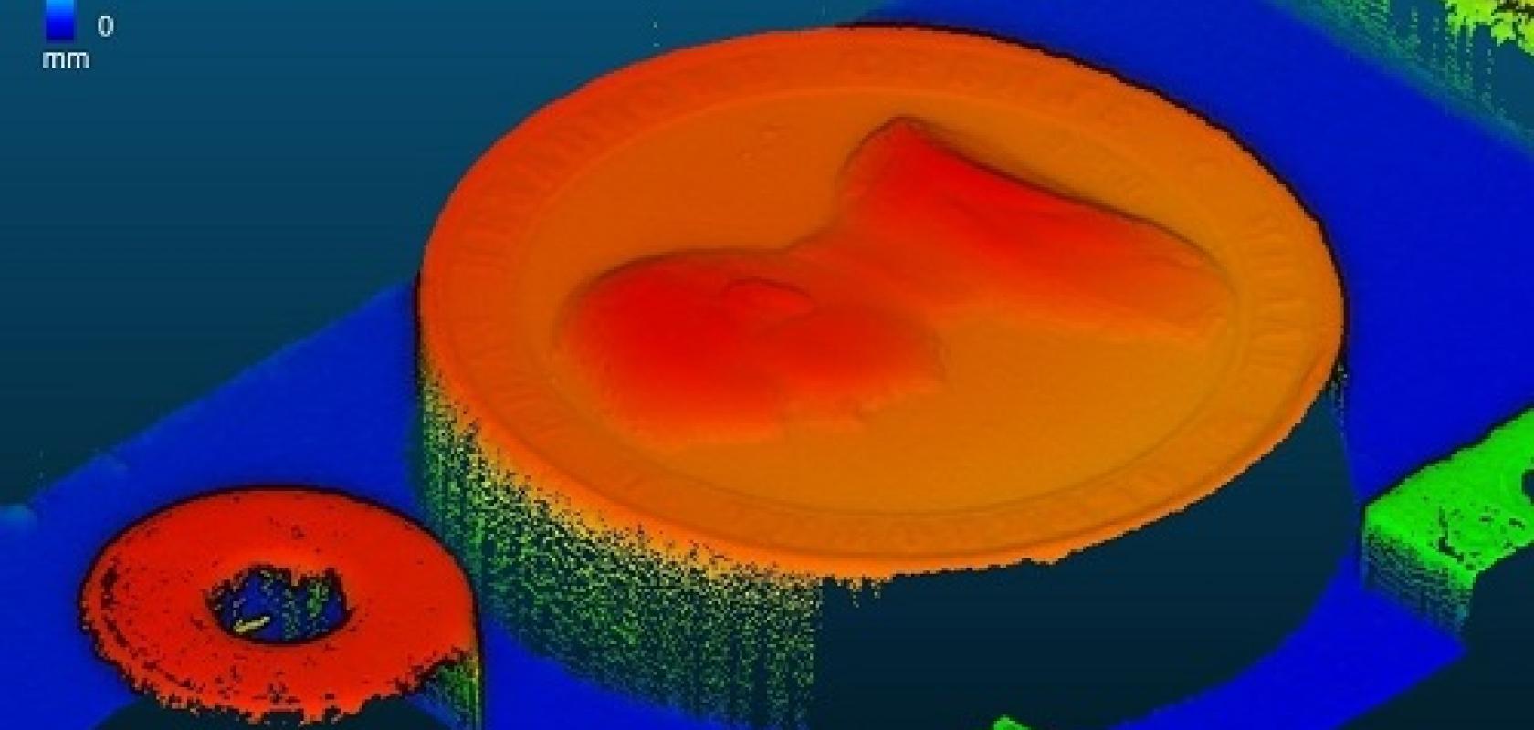
The technique can be scaled to different optical resolutions. Thanner explains that, often, the group uses an optical resolution of about 20μm per pixel, because it’s easy to handle. ‘With this we can demonstrate most of what we want to demonstrate,’ she says. ‘We often use coins to illustrate the feasibility of the technology because they have metallic, glossy surfaces and a really fine surface structure. We can reconstruct this very well with inline computational imaging and it demonstrates its comparison with the technical feasibility of other technologies quite well.’
Enhanced, rectified 2D images produced by inline computational imaging. Credit: AIT
However, for when 20μm isn’t enough, AIT has developed a microscopic inline computational imaging setup where resolutions of 700nm per pixel can be achieved.
‘This is especially interesting for inspecting ball grid arrays – a type of surface-mount packaging used for integrated circuits – where you can reconstruct the balls of the array,’ Thanner explains. ‘But then we are very limited in depth range because it is like a traditional optical system, where the smaller the resolution is, the smaller the depth range is. But this microscopy solution can also image printed surfaces very well.’
Traditionally, AIT has worked in security print inspection – it developed the first banknote inspection solution more than 20 years ago. Therefore, the AIT often relates its technologies back to this application, Thanner says, and uses it as a demonstrator application. The inline computation microscopy solution makes it easy to inspect European banknotes for their fine features, printed so that blind people can feel which denomination it is.Thanner notes that the technology can also be used to inspect burrs in sheet metal production, or really any surface – glossy, matt, low texture, holograms – with tiny features that need to be reconstructed in detail.
Though a large majority of machine vision applications are solved using two-dimensional imaging, machine vision applications using or requiring 3D measurement and inspection are growing significantly. Numerous techniques are used for extracting 3D information from scenes. Let’s mention structured light (including laser-scanning based triangulation), stereo or stereoscopic vision and time of flight sensors.
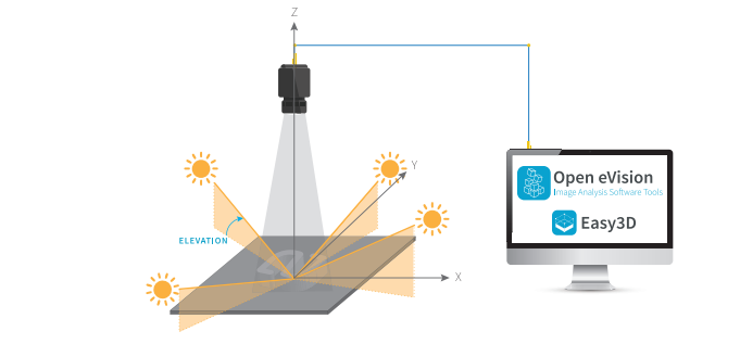
Figure 1. Inspected object with multiple lighting angles in front of the camera
One, probably lesser known, of these techniques is Photometric Stereo. Euresys’ Photometric Stereo function estimates the orientation and albedo of each point of a surface by acquiring several images of the same surface taken from a single viewpoint, but under illumination from different directions. The different images are acquired in sequence, in synchronisation with the lighting, thus requiring only one camera.
Photometric Stereo is suitable for the detection or inspection of details (be they defects or information) present on the surface of objects. The Photometric Stereo algorithm is available in Euresys’ Open eVision Easy3D library. It can be used as a preprocessing phase before other operations, such as code reading (with the EasyMatrixCode, EasyQRCode or EasyBarcode libraries), optical character recognition (EasyOCR), alignment (EasyMatch or EasyFind), measurement (EasyGauge) or defect detection (EasyObject or EasySegment).
How does it work?
For a given vision set up (positions and angles of the object to be inspected, the lights (typically 3 or 4) and the camera), the software tool first requires the calibration on a reference object [(hemi-)sphere], or the manual introduction of the set up’s precise geometric characteristics.
Process From then on, the image capture of inspected objects is performed in multiple steps corresponding to the various lighting angles.
At the user’s request, Photometric Stereo individually extracts a number of variables (normal to the surface, albedo, X & Y gradients, mean and Gaussian curvatures). These are used for the reconstruction/ rendering of the 3D information in the 2D domain, making it ready for further processing by other libraries.
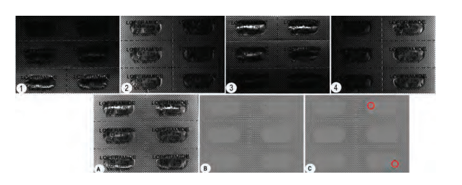
Figure 2. Images of blister under various lighting conditions and inspection
The above Figure 2 illustrates the entire process:
-
The object captured by the camera under four lighting conditions (images 1 to 4)
-
The reconstructed image based on the selected measurements (image A)
-
The isolated subset of data useful for the chosen inspection (image B) (here we have chosen to use the Gaussian curvature information)
-
The results of the inspection by deep learning, using the Open eVision EasySegment library, supervised mode (image C) applied to the image in (B). The two puncture points can clearly be identified.
Optimisation
A few tests allow the identification by the user of the most appropriate variables to recover for is application. These steps will result in the optimisation and potentially speed up a time-critical process.
For example, some detections will require specific linear detections, or alternatively the detection of sharp edges. The specification of a specific Region of Interest (ROI) is also possible. Tuning these parameters to the actual application results in significant speed improvement.
Considering the occasional less than perfect object position, observation conditions or lighting, the function also allows for the compensation of:
-
Ambient lighting (dark image); and
-
Non-uniform lighting (flat reference image).
Conclusion
One can see how the useful information originally not detectable from the original image can be enhanced by Photometric Stereo to be effectively exploited by a standard eVision library (EasySegment in this instance). The Photometric Stereo Imager functionality is available in Euresys’ Open eVision Easy3D Library.
www.euresys.com/en/Products/MachineVision-Software/Open-eVision-Libraries/ Easy3D