Petra Gospodnetic at Fraunhofer ITWM describes her work building a virtual image processing environment to simulate the design of an inspection system
Products come in all shapes and sizes, requiring inspection system integrators to adapt or completely change their machines with each new application. There is no one-size- fits-all vision system; specialised production lines require specialised inspection. It is a complex development process, which works, but it doesn’t come cheap.
However, what happens when a client requires an inspection system for a production line manufacturing a number of small batches of products? There is no smart solution available and if Industry 4.0 dictates an increase in production flexibility, together with a reduction in overall cost, how well can automated inspection keep up? Can costs be cut, inspection systems made less rigid, and the quality of the product improved, while making the integrator’s job easier?
What is preventing automated inspection?
Development of a new inspection system is an iterative process. The pre-study phase is used to develop and adjust the system until it meets a specific set of requirements. When those requirements are met, the prototype goes into production to clean it up and make it ready to work 24/7.
It is the pre-study stage that could be looked at closer. The system is developed in two phases: image acquisition and image processing, with most of the development resources put into image processing. Hardware components and their setup are decided by an engineer based on physical testing and a trade-off between features and cost. It takes a lot of time and effort to test different hardware solutions, and it is impossible to test every potential scenario. Therefore, the engineer chooses what they know will work, even if it has certain drawbacks, and doesn’t spend too much time experimenting because the measurement unit for hardware setup takes hours to change.
Software engineers working on image processing are expected to make their algorithms capable of compensating for potential image acquisition weaknesses. For surface inspection, computer vision research is mostly focused on robust pattern classification, overlooking the need to optimise the acquisition design in order to distinguish those same patterns better. Today, robust classification of difficult patterns can only work in a highly controlled and rigid environment, where as many variables as possible are fixed. To enhance vision systems, these rigid image acquisition constraints must be loosened.
Closing the research gap
Using computer vision, computer graphics, machine learning and robotics it is possible to build a framework capable of design optimisation, which removes the need to assume a fixed image acquisition setup. Currently very little or no research is focused on inspection system design and optimisation.
A virtual image processing framework can overcome this gap in research, by thoroughly testing the acquisition hardware of choice and simulating the end result. Most importantly it makes optimisation of the component positioning possible without actually requiring the engineer to remount the equipment over and over again. Furthermore, computer vision algorithms can be developed and tested on simulated images, along with the acquired ones, overcoming a frequent problem of defect sample acquisition, especially in industries where defects occur rarely, but are critical when they do – airplane blisks and car brakes are two examples.
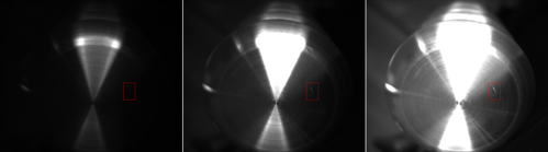
Slight variations in exposure time (from left: 137ms, 700ms, 2,309ms) might reveal defects in some parts of the object, while, at the same time, making other parts unusable because of over or under saturation.
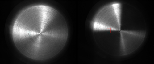
Even slight variations between the angle of the camera and the surface can make a defect completely invisible.
Virtualisation core
The key to virtual image processing lies in the virtualisation core, consisting of two interconnected components: planning and simulation. Simulating what the camera sees can be used to evaluate the design plan of an inspection system. The core is fed by a CAD model – the geometry – of a product, along with different inspection parameters, for example the types of defects, product material, and inspection speed. Based on these parameters, the core will output a set of possible solutions and parameters, which an engineer can then use to build an inspection system, as well as the expected results, for example sensing viewpoints, light positions, and simulated inspection images.
The framework is currently being researched and developed on several fronts in parallel: parametric surface estimation; active model-based position planning; camera lens modelling; position-based defect augmentation; and surface light response modelling. The emphasis is, firstly, on making the position planning accessible to a broader audience, since it is considered to be the backbone of the overall framework. This can then be built on and features added.
The planning backbone will solve the fundamental inspection problem: maximising object coverage regardless of the surface’s geometrical complexity, while producing a quantifiable coverage measurement. The requirement is a CAD model of the product, also known as a digital twin. The model is used as an active component, meaning that information about surface complexity is directly drawn from it and used to generate a list of camera viewpoint candidates – i.e. a list of points in space that might be required to cover all interesting parts of the product. The viewpoint candidate list is then optimised by modelling the complete inspection environment, using physical-based rendering to simulate sensor response and taking inspection parameters such as the number of viewpoints or overall inspection time into account. The final output is a list of viewpoints for both illumination and camera necessary to carry out the inspection.
In the current development phase, the pipeline produces a list of camera viewpoints in order to inspect the entire geometry of the object. The viewpoints are also used for manipulator trajectory optimisation, with a key point being the fact that the choice of manipulator rests solely on the system designer.
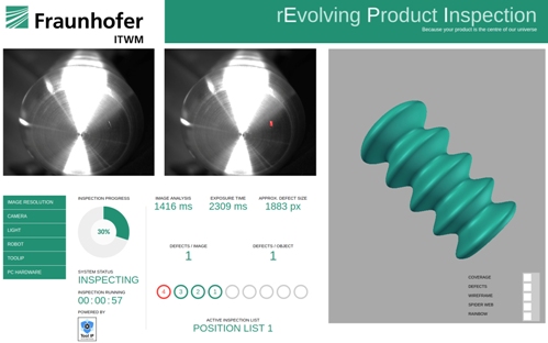
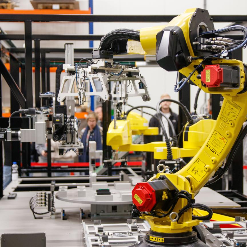
Interface of an inspection system developed for adaptive product inspection. Camera and illumination are mounted on a robot arm.
As mentioned earlier, current inspection systems offer no or very little flexibility when it comes to production lines. Therefore the idea of a flexible inspection system, capable of adapting to small-series production lines is currently just a dream. By developing virtual image processing and implementing it into the inspection system development process, automated inspection will mature. Surface complexity of the product or its actual size will no longer pose a problem when it comes to system design.
The inspection system development phase will be shortened thanks to environment modelling capabilities, reducing the amount of physical testing, which will also reflect on the overall cost – not only will it be reduced, it will also be possible to give a more accurate prediction.
Petra Gospodnetic is completing her PhD at Fraunhofer-Institut für Techno- und Wirtschaftsmathematik ITWM. She presented her work at the European Machine Vision Association’s business conference in June 2018 in Dubrovnik, Croatia.
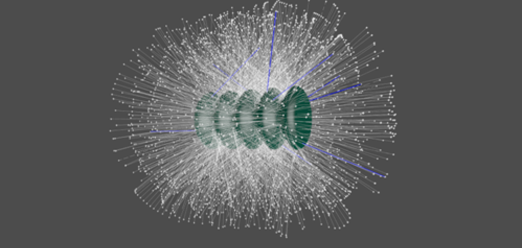
Top image: A list of viewpoint candidates (white), along with the reduction of viewpoints required to cover an object's interesting regions (blue)