Using TurboDrive to Exceed GigE Boundaries
The Linea GigE is the first Teledyne DALSA camera to offer TurboDrive.This technology enables cameras to transmit information at a rate exceeding the constraints of gigabit Ethernet.TurboDrive is a patent pending innovation that uses advanced data encoding techniques that look at the redundancy in the data coming out of the sensor. It uses image entropy based encoding to model pixel information with no loss of information. This enables faster data transmission on the link as each pixel is comprised of fewer bits for encoding.
With new CMOS sensors pushing the acquisition rate, the transmission bandwidth available at the camera interface is often the bottleneck. Frame grabber less camera interfaces, such as GigE Vision and USB3 Vision, are generally inexpensive but lack the increase throughput available using frame grabber based camera interfaces, such as Camera Link, Camera Link HS and CoaXPress. Teledyne DALSA’s TurboDrive technology is an efficient approach to augment camera acquisition rate without including a frame grabber in the system, though this technology equally applies to any reliable transmission medium (i.e. the communication link offers provision for forward error correction or packet resend).
Machine Vision cameras have traditionally used absolute encoding over 8 to 16 bits to transmit image information. For instance, in 8-bit, each pixel takes a value ranging from 0 (black) to 255 (white). TurboDrive relies on localized relative encoding to examine each pixel in its context before encoding it. This generates a more compact encoding of the pixel information and enables TurboDrive to be more efficient by packing the same information in less bits. When combined with a reliable transmission link, TurboDrive rates can increase from 120% to 235% of the nominal channel speed.
This primer aims to explain what TurboDrive can do to help your application and to characterize the transmission speed increase relative to the measured image entropy for a large set of typical industrial inspection images. A mathematical model is presented to show the expected amount of throughput increase that can be realized using TurboDrive.
Image entropy
Image entropy measures the level of randomness of the image: the more uniform the image, the easier it is to encode. When the image entropy is very high, it means it contains a lot of information and is thus more difficult to encode in a compact way.
Let’s assume a data source (the sensor) for which each acquired pixel is independent of the previously acquired pixels. Each possible pixel value has a probability of occurrence Pi. The information provided by a pixel with a low probability of occurrence (i.e. a pixel that is different from the crowd) is thus higher than the information of a pixel with a high probability of occurrence.
In this document, we define image entropy using the following equation:

Equation 1: Image entropy
Where Pi is the probability that the pixel value is equal to ‘i’,and log2 is the base 2 logarithm. For probabilities smaller than 1, the log2 is thus negative, hence the need to put the negative sign in front of the summation. The larger the probability, the closer its log2 is to 0 (remember that a probability is always smaller or equal to 1.0). This shows that pixel values with lower probability of occurrence are the largest contributor to image entropy.

Figure 1: log2(x)
The above equation can be directly computed from the image histogram. A histogram is a representation of the distribution of pixel values from a given image. Each time a specific value appears in the image, the histogram column for that value is incremented by one. The histogram can thus be used to provide the probability distribution of each possible pixel value.

Figure 2: Histogram example
It is clear from the above chart that a uniform image with a single intensity would have all its pixels sharing the same value. Its histogram would thus be represented by a single peak. And its image entropy would equal 0, since the probability of occurrence of that solitary value would be equal to 1.0, and log2(1.0) = 0. To fully describe such an image, one only needs to know the common value of all pixels. You can see that encoding such an image does not require too many bits of information! Real images might not be that simple, but most of them present redundancy: specific pixel values have a larger probability of occurrence. This principle is one of the basic building blocks of TurboDrive.
In short, image entropy represents the theoretical lower boundary of the average number of bits necessary to encode each pixel from the image. So the lower the value, the more effective the packing that can be achieved by TurboDrive.
Leveraging neighbourhood effect
Image entropy is the first principle used in TurboDrive. But to reduce even further the number of bits required to encode pixel information (with no loss of information), TurboDrive considers the neighbourhood effect. The neighbourhood of a pixel is the collection of pixels that surround it. Although the exact distance of a neighbour can vary, in this analysis, we will limit our example to the adjacent pixels (i.e. those that directly touch the reference pixel).
For most pixels, there is little pixel to pixel variation and a lot of redundancy. Therefore, it is possible to efficiently use the information of the adjacent pixels to more efficiently encode the reference pixel.
One way to see this is looking at a high-pass 2D filter implemented using a convolution. A simple high-pass filter has the sum of all of its coefficients equal to 0. The filter we use in our model has a 3x3 mask and it provides the largest weight to the centre pixel.

Figure 3: 2D high-pass filter
The result of this filter provides the difference between the reference pixel at the centre, and four of its closest neighbour. It can be seen that, for a uniform image, the 9 pixels have the same value and the result out of this filtering operation is 0. Essentially, the less pixel to pixel variation, the smaller the value output by this high-pass filter. One can intuitively understand it takes less bits to encode a small value than to encode a large value. Obviously, it is possible to play with the weights of the 9 filter coefficients of this model to adapt to the image content.
By exploiting image uniformity, TurboDrive uses localised relative encoding rather than absolute encoding. This is more efficient when neighbour pixels present a high level of correlation. The result of this high-pass filter operation is then used as input to the image entropy step to further minimise the image encoding size. This ensures a compact representation that keeps all the information present in the original image. Using this approach, the theoretical throughput improvement on the transmission medium using localised relative encoding is given by:

Equation 2: Throughput increase
In the above equation, the numerator is typically equal to 8 bits, while the denominator is given by the result of Equation 1 after application of the 2D high-pass filter given in Figure 3.
Figure 4 illustrates this problem for an 8-bit pixel: a camera transmits the binary value 11010001b = 209d. During data transmission, bit 6 changes from a 1 to a 0. The receiver thus see the binary value 10010001b = 145d. The displayed pixel is thus much darker than what was captured by the sensor by a factor of 64 gray levels on a scale of 256 levels. This is a significant error that would be clearly visible in the picture.
Transmission link requirements
A typical machine vision camera encodes the pixel information using absolute encoding. This means that each pixel is fully described by itself and there is no additional need of information to decode it. The numerical value represents pixel intensity. This approach has the benefit that if a transmission error occurs, then the receiver can easily skip the erroneous pixels. The drawback is that this type of encoding requires more bits than what is truly necessary, based on the image entropy principle explained earlier.
So if absolute encoding is not optimal, how come is it so popular in machine vision? This stems from its simplicity and the fact that analog and Camera Link offer a transmission channel that does not deal with transmission errors. Let’s use the example of Camera Link. This camera interface was introduced in October 2000 and it has been popular ever since, mainly due to the fast data throughput it offers (up to 850 MB/s). But a lesser known fact is that Camera Link does not offer any robustness when faced with bit errors: if a bit is corrupted during the transmission, the frame grabber has no way to detect the problem or to notify the application. The affected pixel takes an incorrect value. The magnitude of the effect is dependent on whether the corrupted bit is closer to the most significant bit (larger impact) or nearer the least significant bit (smaller impact). Camera Link does not offer any checksum, data retransmission or forward error correction mechanism. But don’t think reliable transmission is a characteristic of older camera interfaces. Even CoaXPress 1.1, a more recent camera interface, is limited to error detection with no guaranty of image transfer robustness.

Figure 4: Bit error during transmission
Because of its reliance on adjacent pixels, TurboDrive requires reliable transmission channels, such as those offered by GigE Vision, USB3 Vision and Camera Link HS. Any transmission error is then managed at the transmission link layer: the TurboDrive decoding engine always see an error-free digital signal. If the channel was not reliable, a transmission error in a pixel would spread to its neighbours, creating a cluster of incorrect values. This is the reason why TurboDrive has been designed to be used with reliable transmission media.
The above principle is necessary because TurboDrive relies on relative encoding. Hence the information encoded in one pixel is not sufficient to fully describe the pixel (like for absolute encoding). Therefore, supplemental information from adjacent pixels is necessary to reconstruct the pixel. The data are identical before encoding and after decoding, but a more efficient data packing can be realised by considering the neighbour effect.
Breaking the bandwidth barrier
The above 3 principles are sufficient to implement TurboDrive, but incomplete to exceed the camera interface maximum throughput. Most machine vision cameras have been designed to acquire images at a frame rate that does not exceed the transmission link capacity. Image acquisition is thus not decoupled from image transfer. Again, this approach stems from analog and Camera Link cameras.
To take full advantage of TurboDrive, the camera must acquire at a rate that is faster than the nominal transmission rate when absolute encoding is used. We call this the “burst mode”. The camera can then leverage the localised relative encoding scheme of TurboDrive to pack additional information on the transmission link. This enables faster image acquisition and transfer. A GigE Vision camera can thus exceed 115 mega-pixels per seconds because each pixel takes less than 8-bit to encode.
To realise this benefit, the camera must implement onboard buffering. These buffers are used to accumulate pixel information. This has the benefit of compensating for variability in the encoding level: buffers smooth out encoding variations to help create a nice average transmission rate that fits within the boundary of the camera interface maximum throughput. And the camera can use dead times between images to continue transmission and drain the content of those internal buffers, further exploiting the transmission link.
When sufficient buffering is available, the goal is for average throughput, after relative encoding and including dead time, to fit within the maximum transmission speed of the camera interface. All Teledyne DALSA TurboDrive-enabled cameras support this 4th principle to give you improved acquisition rate that ensures the maximum performance from the sensor.
Performance analysis
In this section, we compare TurboDrive against the theoretical mathematical model described above. The objective is to characterise the actual throughput increase of TurboDrive when used with typical machine vision images. To realise this, we will use Octave, a freely available interpreted language intended for numerical computations and quite similar to Matlab®. Octave will be used to compute the throughput improvement for the mathematical model. Teledyne DALSA offers a tool to determine throughput improvement using TurboDrive. By feeding the same images into the mathematical model and into TurboDrive, a linear relationship is created to link the 2 approaches. This equation can then be used as a predictor to obtain the expected performance improvement of TurboDrive by using the simpler mathematical model.

Figure 5: TurboDrive compared to the model
The listing below provides the Octave script file to compute the theoretical throughput improvement achievable by the mathematical model presented in this primer. All the image files to examine must be placed in the same folder. The script iterates through those files and reports the throughput increase.

Figure 6: Mathematical model
The same set of images is fed into the TurboDrive tool to determine the throughput improvement using TurboDrive Performance Tool implementation.

Figure 7: TurboDrive Performance tool
We have run both methods on a set of 98 images captured from various machine vision applications: barcode, OCR, ITS, electronic inspection, etc. The graph below compares the throughput ratio of TurboDrive (y-axis) against the theoretical model (x-axis).

Figure 8: Throughput increase
This graphic shows a significant linear relation between TurboDrive and the mathematical model. The correlation is sufficiently high that the model can be used as a good predictor of TurboDrive performance.
From this data, we perform a simple linear regression. This establishes the equation between TurboDrive and the mathematical model using the least square estimator.

Equation 4: TurboDrive throughput increase
The determination coefficient (R2) is equal to 0.636. This coefficient indicates how well the data fits the statistical model. In this case, 63.6% of the variation of the TurboDrive throughput increase can be predicted from the model.Equation 4 is valid when Throughputmodel is in the range that extends from 1.25 to 4.0. One can use this equation combined with the mathematical model expressed in Figure 6 to obtain a coarse approximation of the average throughput increase that TurboDrive should provide for the given image class. With this figure in hand, you can estimate what TurboDrive can do to speed up your application.
TurboDrive benefits
Teledyne DALSA introduced TurboDrive with the release of the Linea GigE linescan camera and Sapera LT 8.0 in Spring 2015. By leveraging the technics explained in this primer, the Linea GigE can push its throughput to break the 115 MB/s normally seen in this class of products.

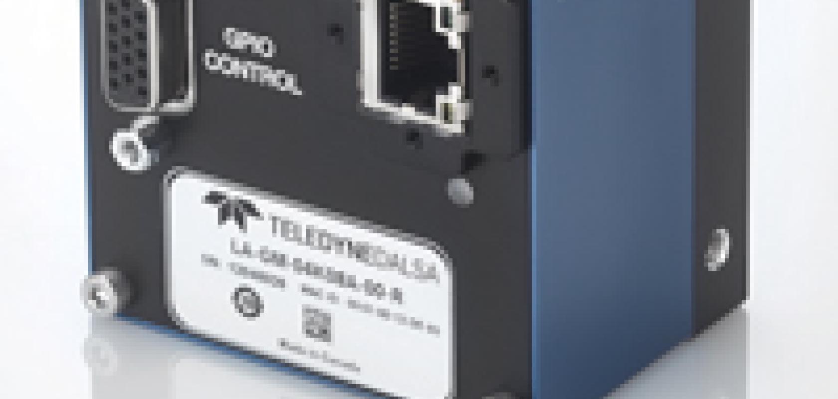
Figure 9: Teledyne DALSA Linea GigE
For instance, the Linea Mono 4K GigE is normally limited to 26 kHz because of the gigabit Ethernet link speed. By activating TurboDrive and considering the dead time between virtual frames, the line rate can reach 80 kHz for scenes with low image entropy. This is the same line rate offered by the Linea Camera Link model, but with the added benefit of the GigE Vision long cable and lower system cost (no frame grabber required for GigE Vision).

Figure 10: Linea camera models
One important benefit is that TurboDrive is totally transparent to the application source code: all the work is performed within Teledyne DALSA GigE Vision driver, a building block of Sapera LT. To activate TurboDrive, one simply needs to set the Turbo Transfer Mode to TRUE in CamExpert (see Figure 11), or to directly access turboTransferEnable GenICam feature. When TurboDrive is enabled, Sapera LT communicates with the camera to determine which version of TurboDrive it supports and they agree on the encoding scheme. This means an existing Sapera LT application can directly benefit from TurboDrive without the need to recompile or modify its source code. The data put in the host buffer is identical, TurboDrive enabled or not. But the difference resides in the maximum achievable throughput.

Figure 11: Activation of TurboDrive in CamExpert
Another use of TurboDrive is with multi-camera systems. Using an Ethernet switch, it is possible to combine image streams coming from multiple cameras onto a single network interface card (NIC), as long as the aggregated throughput from these cameras, after TurboDrive encoding,does not exceed the maximum link speed of 115 MB/s for GigE Vision. For some machine vision systems, this might be more cost effective than using multiple NIC.

Figure 12: A multi-camera system
Conclusion
When using a reliable transmission medium, such as GigE Vision, it is possible to switch from traditional absolute encoding, where each pixel is represented by its intensity, to a more efficient type of data encoding based on redundancy, with no loss of information such that the decoded image is bit for bit identical to the image captured. TurboDrive leverages the combined effect of image entropy and adjacent pixels variation to increase the camera throughput. We have demonstrated that improved performance level typically ranges between 120% to 235% for the image set used in this experiment. For the 115 MB/s available in standard GigE Vision over a gigabit Ethernet link, this represents an equivalent transmission bandwidth of 138 MB/s to 270 MB/s with TurboDrive enabled. And TurboDrive is totally transparent to the application.