The term 3D vision is a very broad one and encompasses many different technologies. Dr Lutz Kreutzer, manager of PR and marketing at MVTec Software, notes that there are two main objectives for 3D imaging systems, both of which can be achieved by different means: 3D alignment, or finding the 3D pose (position and orientation) of an object, and 3D reconstruction, which is determining the 3D shape of arbitrary objects. ‘To solve a 3D vision problem, it is often necessary to employ and combine different technologies,’ he says. MVTec’s Halcon software platform provides functionality for various ways of acquiring 3D information, which can be laser-based, stereo-based using two or more cameras, monocular 3D, time-of-flight, and Moiré interferometry, among others.
One of the more established 3D techniques, and one commonly used in industry, is laser triangulation. Here, a laser line is projected onto the object and a camera images the deviations in the laser as the part moves across the beam to build up the 3D shape. The technique creates a 3D elevation map of the object and is commonly used for defect detection, measuring volumes, or measuring elevation dimensions. Tyre inspection is a good example of where a scanning laser can be particularly advantageous, as it’s difficult to identify any defects or read a black serial number on a black tyre with standard 2D techniques. Food processing is another area that has adopted laser-based 3D vision. The technique is good for estimating volumes of foodstuffs, such as chicken breasts, as they move along a conveyor belt to portion the food accurately.
A 3D setup based on laser triangulation will give a height output in pixel values. Pierantonio Boriero, product line manager at Matrox Imaging, comments that it’s difficult to get the mechanical setup correct with laser-based ranging. ‘Firstly, there are certain constraints on how the laser is projected and where the camera is positioned in order to achieve the desired measurement accuracy and range, which tend to work against each other,’ he says. The Matrox Imaging Library (MIL) contains various 3D vision software tools.
According to Boriero, a lot of effort has gone into making the calibration process for laser triangulation as straightforward as possible without compromising accuracy. There are many ways of calibrating the system, but often a positioning stage will be used to move a known object accurately through the field of view. From this, the system can build a lookup table for converting xyz pixel values to real-world coordinates. Anders Murhed, product unit manager, advanced vision at Sick IVP, notes some disadvantages with this type of calibration method: ‘The object has to be moved very accurately and the stages can be expensive. It is also often not practical to have to use this equipment to recalibrate cameras on production lines.’
Sick has developed a saw-tooth calibration tool that the user can move back and forth across the laser plane by hand to build up the calibration matrix. By programming the vision system with the dimensions of the tool’s teeth, the matrix can be produced without the absolute position of the target.
For making very accurate 3D measurements, Stemmer Imaging’s Common Vision Blox (CVB) software now incorporates Metric 3D, a metric calibration system for laser triangulation. The tool uses a complex calibration process that provides accuracies beyond that of standard laser triangulation calibration methods, which use a simple sum of pixels defining the area of the slice.
The Metric 3D system profiles a known object that changes in size, rather like a cone with sharp edges, moving from small to large and then small again, so that every single point in the 3D space is calibrated individually. ‘In a standard system,’ explains Mark Williamson, sales and marketing director at Stemmer Imaging, ‘if the camera is at a slight angle or the laser is not completely perpendicular it will affect the accuracy at different points in the 3D space. Metric 3D can achieve more than 10 times the accuracy of standard calibration methods, because the technique calibrates out any errors in the system caused by slight mechanical misalignment.’
CVB also includes Merge 3D, which uses data from two cameras positioned on either side of the laser to give more information and avoid dead spots. Complex parts containing multiple peaks and troughs or sharp steps in their geometries can result in occlusions, in which the laser beam is blocked by the part. The two cameras are correlated and calibrated using Metric 3D, so that, even if each camera provides different area measurements, the software compensates for it, because every single point has been calibrated and cross-correlated.
Stemmer Imaging has recently implemented a 3D system at a food processing application, in which the produce was imaged at 360° to get a very accurate measurement of the volume. ‘Many food products don’t have a fl at base and to get an accurate measurement of volume requires 360° 3D imaging,’ says Williamson. In this project, the Merge 3D capability was extended to use data from three cameras – one from the top, one from the bottom left, one from the bottom right. The food item moves over a conveyor with a gap in it and, using a complete laser sheet, both the top and underside could be imaged to create one integrated slice area and volume measurement.
The system is calibrated to identify the alignment between the three cameras. ‘In theory, a system could be built without any errors if the cameras were positioning very exactly, but that’s impossible in a manufacturing environment,’ comments Williamson. ‘The calibration tool allows the system to not only be calibrated for area, but also to be calibrated for the interaction of multiple views of the same object.’
3D vision, 2D processing
‘Once the elevation map has been generated, a lot of traditional 2D tools can be applied to carry out the analysis,’ says Matrox Imaging’s Boriero. An elevation map is effectively a 2D image in which the intensity information is replaced with the elevation information. A blob tool can be applied on a height map to fi nd the object, and multiplying the height with the area will give the volume, for instance. Murhed of Sick IVP comments: ‘Often, more specialised 3D tools are needed to engineer an effective application and a combination of 2D and 3D processing tools will typically give the best result.’
Robotics is one of the big areas for 3D vision because of the flexibility it provides to manufacturing. Random bin picking, for instance, is very hard to do with 2D cameras because objects cast shadows and are lying on top of each other at different angles. In the past, robots were blind workers, says Kreutzer of MVTec; they only operated at set coordinates. The integration of 3D vision means that the xyz coordinates of objects lying in random orientations are fed to the robot arm, allowing greater flexibility for pick-and-place applications. One such system, using Point Grey’s Bumblebee XB3 stereo camera along with Cognex’s 3D-Locate software, was demonstrated at the Vision Show in Boston at the end of May. The system provided real-time 3D positional information to determine each part’s 3D orientation, including parts that were stacked or tilted, for such applications as vision-guided assembly, logistics, pick-and-place, and inspection.


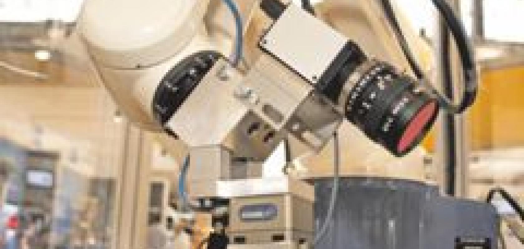
Left: 3D reconstruction of an object using the Matrox Imaging Library. Right: Laser triangulation setup using a camera from Sick IVP.
‘Laser scanning is used heavily in industry, while monocular/stereoscopic techniques are particularly suited to robotics applications,’ says Boriero. Stereoscopy uses two or more points of view to retrieve the 3D position of a feature. It requires that a given location be identified in each view, which, according to Arnaud Lina, manager algorithm development team at Matrox Imaging, is the challenging aspect of the technique. Once the position is located, then, after calibration, lines of views can be projected in the 3D space and where these lines cross is the position of the part.
One stereovision approach is dense stereoscopy, where every pixel in the image is associated in 3D space. However, Lina explains that for a flat surface it becomes impossible to associate one pixel in the first view with another pixel in the second view correctly, resulting in areas with errors. A second approach operates by locating well-defined geometries in each view, such as edges or corners, and associating those between the views with a pre-reasoned knowledge of the part. ‘Not every pixel is associated, but only the pixels corresponding to those known geometries,’ says Lina. A stereoscopic vision system guiding a robot handling a car door, for example, can use the features of the door to determine how to pick up the part.
An object can also be imaged in 3D using only one camera (monocular 3D), but only if everything about the geometry of the part is well-known. The dimensions and relative positions of a minimum of four or five features on the object must be known, according to Lina, to locate the part in 3D space with only one camera.
‘The challenge for stereoscopic imaging is to calibrate the vision system as part of a robot cell,’ comments Boriero. ‘Not only does the camera have to be positioned with respect to the real world, but the camera has to be positioned with respect to the robot.’
The advantage with stereoscopy is that it provides a 3D snapshot; the object doesn’t need to be moving. However, according to Murhed of Sick IVP, resolution is often a limiting factor in stereovision, whereas laser triangulation generally provides higher resolution. ‘Laser triangulation provides a robust height map compared to stereoscopy, which requires high contrast to determine the height value,’ he says.
‘Stereovision is suited to robotic applications in which the objects are large and it’s not critical how they are handled,’ Murhed states. Sick has developed, although not released, a laser triangulation system using a sweeping laser line for robot bin picking. By adding a prism on the unit, the laser line can be moved over the bin to obtain a very accurate 3D height map of its contents. ‘This system is not dependent on the object’s contrast, as is the case with stereovision,’ he adds. According to Murhed, Sick has evaluated both stereovision and laser triangulation as potential solutions for random bin picking, concluding that the laser-based method is more effective.
3D overlaid with 2D
Sick’s MultiScan technology combining 3D profile information with 2D features in the output from a single camera, is a further 3D imaging tool.
‘The 3D shape of an object is critical to many applications, but 2D images are also important,’ comments Murhed. The company’s ColourRanger camera can provide RGB colour information along with the 3D elevation. Image processing can then be applied on a stack of six feature images, one containing 3D information, three containing RGB, and two looking at the level of light scatter, for example.
The technology has been employed to grade wood based on information about the shape of the wood, but also on surface defects like knots and stains. Scatter information can be combined with greyscale images, for instance, to distinguish between knots and stains. Using the information from the different feature images, it is possible to carry out an almost 100 per cent grading of the wood.
‘With any machine vision task, the key is to capture good images that enhance the features of interest,’ comments Murhed. ‘One 2D image will always be a compromise and not all the features will be enhanced. The MultiScan approach allows a number of images to be captured, each enhancing different features.’
