Machine vision’s success rests on its ability to highlight features in an image, and illumination is key here. Regardless of the amount of processing power available, it is impossible to identify a feature in an image if it is not visible at the point of capture because the lighting is inadequate.
Computational imaging (CI) aims to overcome this issue. It is a technique whereby a sequence of images are captured, each with different lighting or optical configurations. Data can then be extracted from each image and merged to create a single, high-quality output that contains details relevant to a particular application. Hence, different combinations of illumination – varying light direction, angle, wavelength, intensity, focus, polarisation or scattering – can bring out different features in an image.
Fast sensors, high-speed data interfaces, and cheap computing power mean that CI is now a viable imaging method. Two common CI techniques are high dynamic range and stereovision, the first combining multiple exposures to produce a single image with increased dynamic range, and the second combining images from two different viewpoints to produce a 3D image. Other CI techniques include extended depth of field imaging, ultra-resolution colour imaging, and photometric stereo imaging.
The lighting firm CCS has developed a range of lights dedicated to CI. For example, the firm’s ring lights have been designed to offer four independently controllable quadrants, making them suited to providing the multi-directional lighting required to perform photometric stereo imaging.
Photometric stereo, according to Marc Landman, senior technical advisor at CCS America, is currently one of the most widely adopted CI techniques in machine vision, with most vision firms now having an implementation of photometric stereo in their software. It is used to extract relevant 3D features on the surface of an object that would otherwise be difficult to capture in an image under normal lighting conditions.
Landman highlighted the greater awareness and uptake of CI in a presentation he gave about computational imaging as part of the AIA’s recent Vision Week, which was held online in May in place of the US Vision Show. He told Imaging and Machine Vision Europe that machine vision manufacturers are now responding to this trend with CI-compatible hardware and software.
Photometric stereo works by capturing at least four images of an object, with light coming from a different direction in each image – for example, north, east, south and west, Landman explained. This throws shadows on any 3D structures on the surface, which are captured in four different directions in the four images. The edges and the shadow information can then be merged using a photometric algorithm, and the surface relief can be extracted three dimensionally. This greatly accentuates the features on the surface.
An example of where this can be used is for inspecting pharmaceutical cartons. Under conventional lighting, both the printed universal product code (UPC) and embossed date or lot code can be seen, but they are superimposed, making it virtually impossible for both to be read by a machine vision system. The problem can be overcome with photometric stereo.
The carton flap is imaged sequentially using CSS’ four-segment ring light. Photometric stereo algorithms are then used to combine the images to produce a shape image and a texture image of the flap. The shape image contains only the depth data obtained from the shadowing cast on the embossed text, and therefore reveals the date or lot code, while in the texture image only the UPC code is readable. The output can then be read using a conventional OCR algorithm.
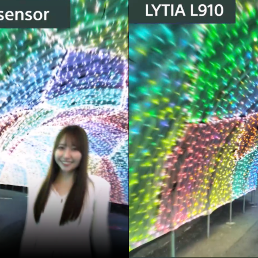
CCS has developed both a white and full colour segmented ring light, the latter also being ideal for ultra-resolution colour imaging, another CI technique of growing interest. It works by taking three separate 8-bit red, green and blue images with a monochrome camera and then merging them to output a high-resolution 24-bit composite colour image. Composite colour images are much sharper than those produced by a single image capture with a Bayer or mosaic colour camera, as every pixel on the sensor is used to form the image – there is no interpolation of pixels as would be the case when using a Bayer filter.
‘The images are of similar quality to those from three-chip cameras without the expense, special prism or lens limitations, and are at much higher resolutions than that of available three-chip cameras,’ remarked Landman. ‘When zooming in on the composite image, edges appear much sharper, contrast and colour may be improved and noise is reduced compared to an equivalent Bayer colour image. In addition, other artefacts such as red and green aliasing are eliminated.’
While this CI technique has been around for a while, it has not been commonly used in factory automation, according to Landman. Now, however, thanks to fast cameras and data interfaces, and higher computational power being more widely available, it is becoming more practical to use ultra-resolution colour imaging in online industrial applications.
‘It is now possible to do this at high frame rates,’ Landman said. ‘We are strobing our red, green and blue full colour ring light sequentially at 180fps – 60fps red, 60fps green and 60fps blue – merging those together, and outputting the 24-bit colour image at 60fps, using a 12-megapixel CXP4 monochrome camera with a CXP4 frame grabber.’
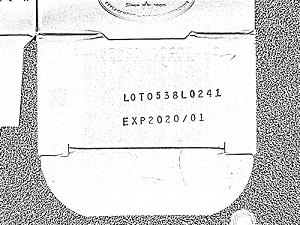

Photometric stereo image (left) can be combined with a texture image (right) to read different pharmaceutical packaging codes. Credit: CCS
Together with other CI techniques such as extended depth of field and HDR, photometric stereo and ultra-resolution colour imaging are already used in the automotive, pharmaceutical, food, healthcare, packaging, electronics and wood industries. They are being used for applications as varied as identifying small surface defects, revealing overlaid text and barcode information, reading braille characters, inspecting tyres, improving colour fidelity, highlighting pinholes in food packaging, and imaging objects of different heights in the same field of view.
In addition to ring lights, another key component developed by CSS for CI is its four-channel programmable lighting controller, the Light Sequencing Switch (LSS), responsible for managing the necessary image capturing sequences in CI. ‘The flashing of the light needs to be synchronised with the exposure of the camera, and coordinated with the part moving under the camera while shifting the focus of the lens,’ explained Landman. ‘A tracking algorithm is therefore used to track the object through each frame as it passes under the camera; you can then shift the pixels to merge the images together.’
Further integration needed
Despite the greater uptake of CI in machine vision, Landman believes a higher level of integration between the components involved must first be achieved before it can fully take off in industry.
‘The need for illumination to be integrated within the machine vision system, rather than be a separate function, is so important,’ he said. ‘The way I see it playing out over time is that the multiple components required to perform CI will become more tightly integrated within the camera. That’s the direction I hope this will go in the future. It will require camera, lighting and lens manufacturers to all work together in order to provide this tight integration and improved imaging capability.’
Landman is not alone in highlighting the need to bring the separate components of CI together in one solution.
John Thrailkill, co-founder and CEO of Advanced Illumination – another lighting firm making big moves into CI – also expressed a need for more mature solutions should CI wish to see greater uptake in industry.
‘We have every indication that this is a very powerful imaging technology. However, it’s still fairly new,’ he said. ‘CI has to be easy to implement in an industrial environment, and that hasn’t happened yet. That’s the push that we’re making.’
Advanced Illumination is working with Matrox Imaging to bring all the components required for photometric stereo into an accessible, robust and flexible system. Advanced Illumination’s wide range of lights – including ring lights, bar lights and line lights among others – multi-channel controllers and mounting accessories will be combined with Matrox Imaging’s smart cameras, vision controllers and MIL software to develop the system.
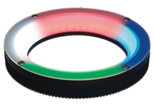
A segmented full-colour ring light from CCS, suitable for both photometric stereo and ultra-resolution colour imaging
Thrailkill emphasised the need for the system to be flexible because of the high level of customisation required for photometric stereo applications: ‘Depending on the application, you may need a very different controller, different lights or a different mounting setup; it’s staggering how much customisation can be required,’ Thrailkill continued.
‘If you don’t make this all easy to understand, or write the application notes explaining it, people just aren’t going to use it.’ Advanced Illumination is therefore working on a section of its website that will contain all the information required for implementing the different components required for photometric stereo imaging.
Thrailkill concluded by reiterating that while photometric stereo is a very practical application with a lot of promise, until all the pieces are brought together, explained and made easy to understand, its uptake in industry will be limited.
‘It’s a lot of work to get it out onto the factory floor,’ he said. ‘We’ve got to walk before we can run, and we are definitely still at the walking stage.’
--
Gone in a flash
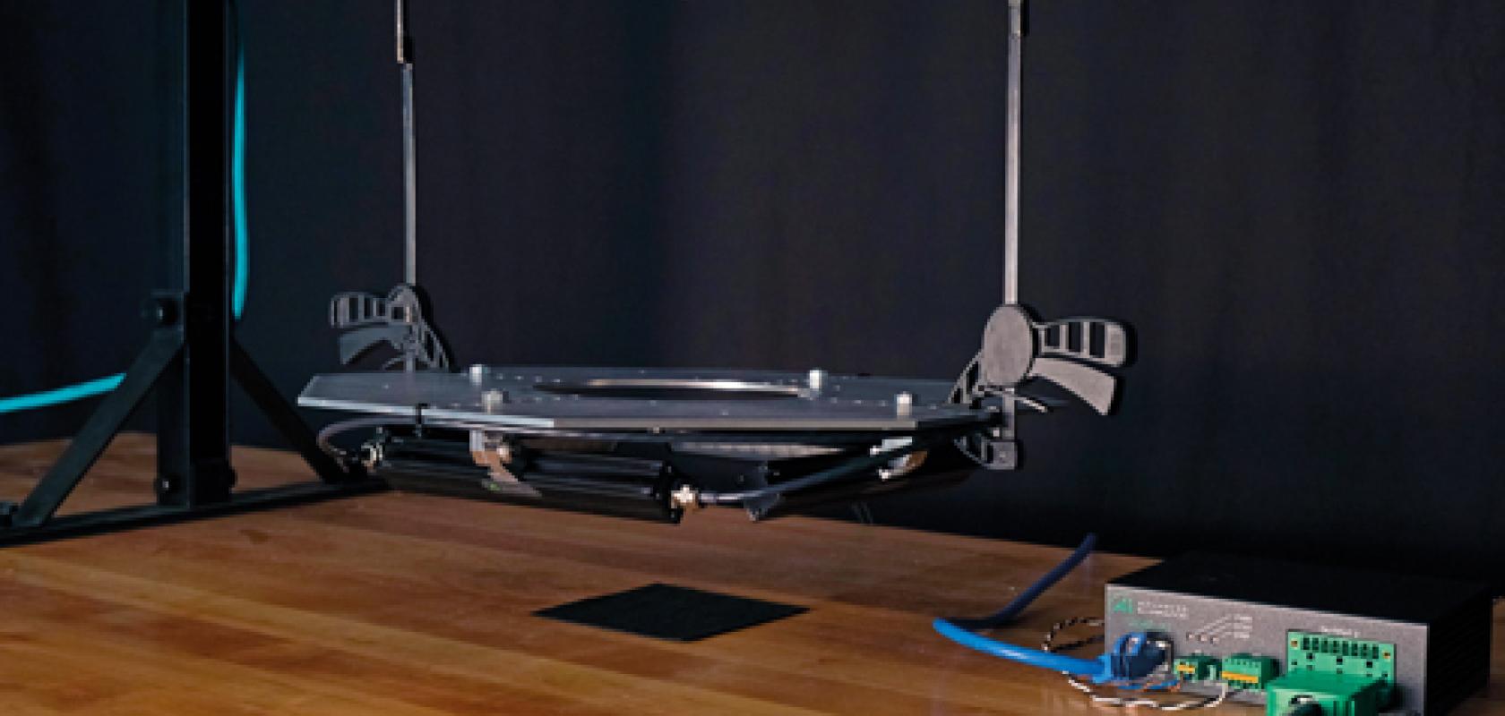
Researchers at the Austrian Institute of Technology (AIT) have developed what they say is the world’s fastest LED strobing system, capable of operating at 600kHz light switching frequency.
The system, called Xposure:flash, was developed to complement the institute’s 600kHz multi-line scan Xposure:camera, which was first demonstrated at the Vision 2016 trade fair. The researchers say that, together, the two solutions address the demand for both faster inline inspection – to match increasing production process speeds – and the ability to acquire multiple types of data from objects using a single camera.
Xposure:flash simultaneously provides high illuminance and high homogeneity, not only for one object plane, but also within a given 3D volume. Two LED panels with white LEDs and LEDs in the near-infrared wavelengths are positioned around the object and are flashed in sequence, synchronous with the Xposure:camera triggering. The camera is therefore able to capture lines in both visible and NIR wavelengths. The system can also be fitted with white LED panels in a way that enables it to be used for casting shadows around the 3D structures on an object’s surface, as is required to perform photometric stereo imaging.

Print inspection of a banknote, capturing a high-resolution colour image (top), a photometric stereo image of the intaglio print (middle), and an OVD image of the hologram. Credit: AIT
The researchers have shown how the camera can be used to inspect banknotes. ‘This is a high-speed printing process, and from this came the demand for developing this high-speed camera and high-speed flashing technology,’ said Petra Thanner, senior research engineer at the AIT’s Centre for Vision, Automation and Control. ‘The notes have to be inspected at several wavelengths – visible, NIR or UV. Our 600kHz camera achieves this by capturing one line in the visible and one line in the NIR sequentially, enabling two types of image to be created for each bank note at incredibly high speeds.’ The photometric stereo capabilities can also be used to image the textured intaglio print on a banknote.
With the rate of both the LED strobing and line scanning in the set-up, it’s important that there is no overlap between the flashing cycles of the different LED panels. As one LED panel switches off before another switches on, its light level must decrease fast enough so that no residual light from it is captured in the next line scan, and that the only light being captured is from the next panel switching on. This created a challenge for the researchers, because when developing the Xposure:camera, the fastest lighting controller available could only operate at 20kHz, rather than at the hundreds of kilohertz required. This meant that the LED panels would only dim over 20µs, whereas the Xposure:camera captures lines every 1-2µs. A dimming time in the range of hundreds of nanoseconds was needed.

Visible and near infrared data stream captured while inspecting a banknote with the Xposure:camera. Credit: AIT
The researchers developed an ultrafast light switching technology, and together with an Austrian firm, built a prototype controller capable of operating at 600kHz. This was achieved by positioning the switching transistors closer to the LEDs, according to Ernst Bodenstorfer, another scientist on the Xposure:flash team at the AIT’s Centre for Vision, Automation and Control. The prototype has a dimming time of 300ns, making it suitable for the ultrafast line scanning of the Xposure:camera.
The Xposure:flash controller measures 93 x 55mm; the LED panels have a footprint of 140 x 17mm. ‘Thanks to it’s small size, the Xposure:flash would be very good for integrating into small spaces, such as in cameras,’ Thanner said. ‘We’d be happy to integrate our technology with cameras from vendors if there is a demand; we are open to collaborations.’
Sponsored Content: Choosing power sources for machine vision lighting
Achieving reliable images needs careful design of lighting control
Experienced designers know that to get great results from a machine vision system you must get a great image. No amount of software processing can recreate data that hasn’t been captured on your camera sensor, and to get that perfect image, time after time, you must have accurate and consistent lighting control. Most machine vision systems use an LED illumination source with one of three drivers: a simple voltage drive, voltage-drive with pulse width modulation (PWM) or a constant-current drive. Simple voltage drive can be the cheapest option but it has significant practical disadvantages due to the way LEDs function. Although LED lights are often specified by voltage, it is actually the current flowing through the light that dictates the brightness obtained and not the supply voltage. As you can see in diagram 1, a tiny change in voltage creates a much bigger change in the current flowing, and the change in current creates a large change of brightness. This important effect means that simple voltage drive cannot be used to accurately adjust lighting intensity. In addition, any fluctuations in the system supply voltage may cause fluctuations in lighting levels.
PWM voltage controllers provide limited intensity control by pulsing the light on and off so that the average intensity is approximately what’s needed. To increase brightness, the light is simply pulsed on for longer. However, PWM also has practical disadvantages. The speed of the PWM cycles dictates how many intensity steps are available for adjustment and it’s usually limited to about 100 coarse levels. The PWM pulses are usually independent of exposure timing which can cause intensity variations between exposures, particularly for fast systems. Diagram 2 shows an example where the timing of the camera exposure and PWM pulses results in the first exposure receiving more than 30 per cent more light than the second exposure. A faster internal PWM clock can reduce this effect, but these high-speed voltage pulses can cause EMC interference in neighbouring systems.
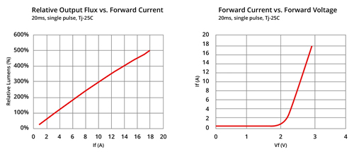
Diagram 1: Relationship between voltage, current and intensity of LED lighting
Constant-current controllers are usually the best choice of lighting drive for LED lighting. They directly adjust illumination levels by accurately controlling the current flowing through the light. There is no fundamental limitation on the number of adjustment steps and a typical Gardasoft controller will provide 3,600 steps of brightness with no risk of EMC interference.
Strobing and overdriving
Continuous illumination can be adequate for some applications. Usually, a light will be set up to below 100 per cent brightness so that illumination can be increased later if needed. Both voltage-drive and constant-current controllers can drive continuous illumination. However, one well-known effect is that as an LED light heats up, the illumination intensity will fall. This effect is often minimised by using the ability of LEDs to be pulsed on briefly so that the light is only illuminated while the image is captured. Pulsing the light prolongs the life of the light, which will degrade with on-time. Pulsing is also an important technique to prevent image blur on fast production lines. Effective strobing relies on obtaining consistent and repeatable square light pulses with rapid rising and falling edges. Sharp edges are more difficult to achieve with a PWM controller, particularly if there is a long cable between the controller and the light. If the pulse edges have a poor profile, the intensity of the illumination is likely to vary between exposures. Constant-current lighting controllers are inherently able to create accurate, repeatable square pulses with sharp rising and falling edges.
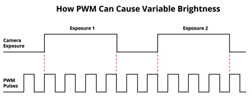
Diagram 2: How PWM can cause variable brightness
A powerful extension of strobing is overdriving, where a current higher than the maximum rating is driven through the LED light. This short pulse can produce much brighter illumination than the maximum specified by the device manufacturer and will not damage the light when a good strobe controller is used. A quality strobe controller will carefully manage the frequency, pulse duration and current to prevent heat build-up that could damage the light. Only constant-current controllers can achieve a safe and accurate overdrive. Voltage-based lighting controllers including PWM versions that supply a standard 24V cannot overdrive lights and those that offer the option of an additional, higher voltage suffer from an unpredictable discontinuity in brightness between the two voltage levels. Most constant-current controllers can operate with complete flexibility in either continuous, strobe or overdrive modes.
High-speed lighting control
Certain applications must have very short camera exposures. High-speed inspection lines and systems using a single imaging station to capture multiple images will need short exposures. Line scan applications also use short exposure times which need precision lighting control. Some more advanced PWM systems offer the ability to synchronise the PWM cycle with the camera shutter to avoid the issues shown in diagram 2, but this can be difficult to implement in practice. Constant-current lighting controllers offer much more flexibility at high speed because they allow the intensity and duration of lighting to be precisely adjusted and are not tied to a PWM cycle.
Author: Jools Hudson, Gardasoft Vision Ltd, Trinity Court, Buckingway Business Park, Swavesey, Cambridge, CB24 4UQ, UK; Tel: +44 1954 234970; E-mail: vision@gardasoft.com; Internet: www.gardasoft.com