We ask four experts to give their advice for 3D imaging best practices
How do you decide if you can benefit from 3D vision, especially on a limited budget?
Inder Kohli, Teledyne Dalsa: ‘3D vision helps solve several inspection challenges that are difficult, if not impossible, to be handled by 1D or 2D imaging techniques. For example, variation in height, defects caused by indentation or bubbling of laminate, measuring object thickness, coplanarity of adjoining surfaces [and] uniformity or asymmetry of extruded parts.
‘Historically, it required specialist knowledge to build and maintain 3D systems using discrete parts. In expert hands, this might yield the desired performance, but over time field support might erode profits. So, customers can benefit from factory-calibrated, fully integrated 3D profile sensors, like Teledyne’s Z-Trak2. When selecting a 3D profiler, users must consider not only the cost of the unit, but also software tools, deployment time and, equally important, in-field service.’
Fredrik Nilsson, Sick IVP: ‘For tasks that involve measuring dimensional features, it is very likely that 3D imaging will be the more cost efficient choice in the end. It will provide reliable measurement even if the parts to inspect are presented at different positions in the field of view. In addition, segmentation of the parts from the background is greatly simplified by using 3D vision, where the contrast issues in greyscale or colour imaging is avoided. Pricing for 3D vision solutions is constantly decreasing, and taking the complete solution cost into account from the beginning – including the maintenance – the choice for 3D may even save you money in the long run.’
What factors should be defined to be successful?
Nilsson: ‘The first thing to consider is if your application has static or moving parts and how accurately you need to measure them. The answer to this has a big impact on the choice of 3D technology and also to the solution cost. Other topics to consider are what height range and width you need to cover, ambient conditions (that is, interfering sunlight or other light sources, vibrations, available space), surface properties of your parts (for example, very shiny, very matt) and what variety of parts can be expected.’
Yoann Lochardet, Teledyne e2v listed other parameters important for choosing a 3D technology to suit the application: ‘Distance range (minimum and maximum); field-of-view; resolution; response time or frame rate; power consumption; lighting budget; compactness of the system; dynamics of the objects of interest (slow- or fast-moving targets); and hardware and software cost and complexity.
‘Time-of-flight is a good choice for a maximum distance of more than 1 to 2m, with moderate requirements on precision and accuracy, and is very efficient in managing uncontrolled ambient setups and with moderate to high speeds. For instance, it is a good choice for machine vision applications (distance ranges up to 5m), for construction mapping (up to 10m), or for ITS applications (20m). On the other hand, laser triangulation is a good choice for applications with fast-moving parts, at a small distance range (less than 1m), and requiring very high accuracy (down to micrometres, or even lower). For example, electronics inspection, wood inspection or automotive inspection.
‘In the end, each 3D technology has its own pros and cons, and some of them are more suitable than others for different applications.’
Svorad Stolc, Photoneo: ‘One of the basic factors that define the achievable acquisition speed is the amount of light. The amount of light the sensor can use depends on multiple factors, including: the power of the light source (in the case of Photoneo 3D vision systems it is a laser that has specific advantages over other illumination types); the working distance (effectiveness of the light emitted by a vision system decreases rapidly with distance from the sensor); parameters of the optics, such as the aperture number, but also the amount of ambient light and other aspects.’
How best do you deal with changing parts or surfaces?
Stolc: ‘In general, the best way to deal with diverse scenes or material types (such as matt, glossy, bright or dark materials) is to set up and control environmental conditions in such a way that the sensor works well – which means that its operational dynamic range matches the expected range of the object’s properties. Environmental conditions may include the amount of ambient light, the optimal perspective with regard to the scene or object geometries, and other aspects. Alternatively, one can opt for sensors that are more robust against diverse working conditions. For instance, Photoneo achieves a high scanning robustness of its sensors by a well-rounded hardware and software design featuring laser illumination, optical filters and algorithms for data post-processing.
‘The robustness of 3D vision systems may be pushed even further – beyond the possibilities of hardware – through AI, the deployment of which is becoming increasingly popular in 3D vision. These approaches are called data-driven as they leverage the information contained in a training data set describing a given problem domain.’
Nilsson: ‘Dealing with changing or mixed parts with both very dark and very bright surfaces in the same scene is best done by high dynamic range (HDR) imaging. In our Ruler3000, we use an adjustable, non-linear imager response function to achieve this. Another way to cope with this is to run the sensor in a dual exposure mode – that is, applying one short and one longer exposure time during the same measurement session.’
How complex is 3D vision? How do you reduce complexity?
Nilsson: ‘3D vision is not necessarily more complex than 2D vision. With a snapshot 3D camera, such as time-of-flight or stereo cameras –for example, our Visionary cameras – you get a 3D image directly and can apply suitable software tools, just as in 2D vision. Furthermore, it is very common to do the image processing on rectified 3D depth-map images, rather than on a 3D point cloud. In this way, the 3D data can, in many cases, be processed with the same tools as for 2D images, which to a large extent removes the complexity issues of image processing.
‘When using laser triangulation, you do need to take the movement of parts into consideration, which slightly increases the complexity. However, once set up, the application can be solved by a point-and-click approach, as in our TriSpector1000 series, which does not require a high level of machine vision competence. Actually, for a range of applications, the solution can be even more simple in 3D vision compared to 2D, as illumination is most often included in the device and you get factory calibrated data (such as in Ruler3000). This is a clear benefit as parts will remain the same size regardless of where in the field of view they are presented.’
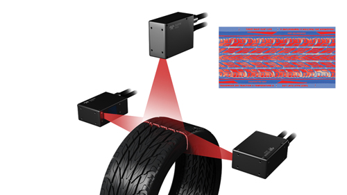
Tyre analysis is one of the applications that can be tackled with triangulation. Credit: Teledyne Dalsa
But Lochardet said: ‘Thinking of imager integration, 3D vision is much more complex than a conventional 2D vision. It involves optics and an illumination system that depends on several parameters (such as distance and reflectivity range, field-of-view, light-power budget and so forth) to fit perfectly with application requirements.
‘Because of this, a deep knowledge is required to build an efficient 3D vision system, or the help of a 3D vision integrator is needed. Teledyne e2v is able to support at all these levels to shorten a customer’s time-to-market and to get the best system to fit the application requirements. For that, we provide both laser triangulation and time-of-flight solutions, ranging from CMOS image sensors and customised camera modules, right up to full system integration support. This includes hardware and firmware development, light and optics assessment, eye safety assessment, application-level simulations, algorithms and factory calibration.’
What are the pitfalls and how do you avoid them?
Kohli: ‘Different 3D modalities have different pitfalls. For example, 3D laser triangulation faces challenges due to occlusion. Since the laser and the image sensor are mounted at an angle it is natural for the 3D profiler to encounter occlusion and shadowing. The simplest and proven technique to overcome the occlusion is to use multiple image sensors to look at the object from the other side. Of course, doing so creates the additional challenge of synchronising the image sensors and then combining the two resulting images to create a corrected image.
‘The other common problem with 3D profilers is reflections. Although there is no single proven method of eliminating reflection, various techniques are used by 3D profilers to mitigate the effects of specular reflections. These include: changing the angle of the incident light, specialised optics, laser intensity management and filters to remove unwanted peaks. The choice of method depends on the type of object surface, operating and performance requirements.
‘Laser speckles are present in every laser because the laser light is coherent. This interference phenomenon is caused by microscopic irregularities of the surface, creating an interference pattern. This pattern manifests itself by making parts of the laser line appear brighter or darker along its length. Such variations limit the uniformity of the laser line limiting the 3D sensor’s achievable accuracy. Several techniques, such as the use of a laser with a shorter wavelength, optics with a bigger aperture and profile averaging can alleviate the effects of laser speckles.’
Nilsson: ‘Other challenges are the unwanted secondary reflections one may get on shiny metal surfaces. Here, a polarising filter in front of the lens can be used to filter out the second order of reflections.’
--
Commercial products
One of Sick’s latest 3D vision products is the Ruler3000. Sick’s Fredrik Nilsson: ‘The Ruler3000 series is well suited for applications with moving objects that require high accuracy even at very high transportation speed. With the different camera variants, we cover small fields of view, for example in electronics production and small part assembly; the mid-sized models are aimed at consumer goods packaging and tyre manufacturing, whereas the models with large fields of view are aimed mainly at log inspection and logistics systems. In particular, the Ruler3000 excels in applications that need coverage of a large height range at high speeds as the camera has the ability to use the full sensor image at 7,000 3D profiles per second. If less height range is needed, the speed increases proportionally to the reduction of sensor image in use.
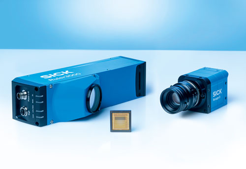
Sick’s Ruler3000 and Ranger3 cameras. Credit: Sick
‘The Ruler3000 is based on laser triangulation but for applications without linear movement, other technologies may be more relevant. The main deciding factors are the frame rate and the resolution needed as there is often a tradeoff to be made between them. For example, a time-of-flight system can run at high frame rates but has limitations in the height accuracy, whereas structured light sensors can achieve really good accuracy at the expense of frame rate. It should not come as a big surprise, but in the end, you need to know your application and its specific requirements really well before you decide what technology to choose - and this is true regardless of 2D or 3D vision technology.’
Teledyne e2v supplies time-of-flight and laser triangulation sensors, while Teledyne Dalsa offers its Z-Trak2 laser profiler. Teledyne Dalsa’s Inder Kohli: ‘Z-Trak2 comes in a wide variety of configurations and laser options to handle a range of parts, from small electronic components to large automobile engine parts, door frames to entire chassis. Applications that require height, width, length, and volume information of moving parts at a close range are ideally suitable for Z-Trak2. The exact model of Z-Trak2 depends on the size and surface properties of the target object, scanning speed, accuracy, and precision of the measurements required.
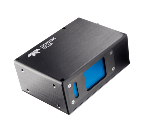
Teledyne Dalsa’s Z-Trak2 laser profiler. Credit: Teledyne Dalsa
‘Z-Trak2 laser profilers offer speed, accuracy, ease-of-use, and help reduce the total cost of ownership by ensuring that systems can be built and maintained with standard off-the-shelf networking parts, making it the right choice for in-line 3D measurement, inspection, identification, and guidance applications.’
Photoneo’s 3D camera, MotionCam-3D, can provide a lateral resolution of 2 megapixels with a depth accuracy of 50 to 900μm across the different models, while being able to capture objects moving up to 144 km/hour. Photoneo’s Svorad Stolc: ‘We reduce the complexity of 3D vision by improving hardware robustness and aim to provide flexible enough APIs and tools to our users. Our sensors feature a highly durable carbon body and they are IP65 rated.’
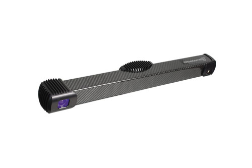
Photoneo’s MotionCam-3D. Credit: Photoneo
Inder Kohli is senior product manager, vision solutions at Teledyne Dalsa; Fredrik Nilsson is head of business unit machine vision at Sick IVP; Yoann Lochardet, marketing manager, 3D at Teledyne e2v; and Svorad Stolc is CTO of 3D sensing at Photoneo.