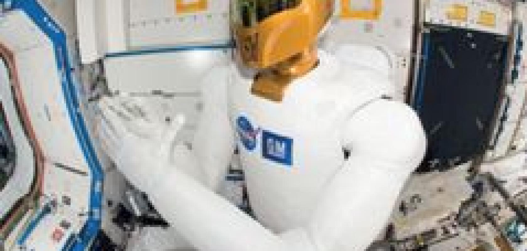
Last year saw NASA retire its fleet of space shuttles, bringing an end to an era of space exploration spanning 30 years. The five shuttles flew 135 missions between them, helped construct the International Space Station, and have ferried astronauts and supplies to the ISS ever since. On its last mission in February 2011, space shuttle Discovery delivered to the ISS, not your regular astronaut, but a humanoid robot, called Robonaut 2 (R2), developed jointly by NASA and General Motors. The robot consists of a head and torso with two arms and two hands. It weighs around 300 pounds and is currently being tested by astronauts onboard ISS, with the aim for it to eventually carry out tasks too dangerous or mundane for humans.
The latest update from NASA is that R2 is being programmed to monitor the flow of air through the space station’s vents to ensure they don’t become blocked, a task typically carried out by the astronauts every 90 days or so. The air flow is measured by holding a gauge in front of the vents. The task is seemingly simple, but to get an accurate reading, the gauge has to be held very steady, which is difficult for a human moving around in microgravity. In addition, the readings can be compromised by the astronaut’s breath disturbing the air flow. By handing the task over to Robonaut 2, NASA hopes to reduce inaccuracies in the readings.
The strength of R2, according to Stéphane François of Computed Vision Consulting, who was one of the vision consultants for Robonaut 2, is that its hands are in some ways similar to a human’s hands in that they can perform very delicate operations, while at the same time being incredibly strong. The technological challenge, he feels, is engineering a level of control in terms of R2’s interaction with its environment.
The types of operation R2 is engineered to carry out typically involve manipulating an object or having the robot use a tool. ‘One of the challenges in programming R2 is that the relationship between object and robot is unknown,’ comments François. ‘You have to combine information from the robot’s various sensors, including vision, with the programming for the control of the hands in order to manipulate the object. The challenge is combining that triangle of hands, sensing, and the environment to enable it to interact with its environment.’
R2’s Flexible Vision System includes a stereovision pair of Prosilica GC2450 cameras from Allied Vision Technologies, fixed in its head. It also has tactile force and finger position sensors in its hands in the form of the Swiss Ranger SR4000 infrared range finder from Mesa Imaging. The range finder performs depth measurements and tactile object recognition. François points out that it’s integrating the range of sensor data with the robotics that enables R2 to carry out a wide variety of tasks.
The various vision sensor data was integrated into the Halcon 9.0 vision library from MVTec Software, which was used to perform all the complex computations in a single development environment.
‘Halcon’s classifiers are used for decision making and to gain an understanding of the relative position of an object from the image data,’ explains François. Halcon’s deformable model was also key in determining the relative 3D pose of an object in order to locate it in the environment. ‘We need to know the position of the hand compared to the object, or what the relative position is of the camera compared to the arm, for instance,’ François continues. ‘This is an accumulation of data – it’s not just information from vision but also data from the robotics side. There is a real exchange of information between the vision and the decision control of the robot.’
François adds: ‘R2 is pushing the development of robotics, trying to accomplish tasks that other robots can’t do. A humanoid robot is in some ways the ultimate goal in robotics, and each iteration like R2 broadens our understanding to enable us to engineer simpler robots that are better adapted to specific tasks.’
Mission to Mars
While astronauts continue to test R2 onboard the ISS, another NASA robot, the Mars Science Laboratory complete with its Curiosity rover, is currently en route to Mars, where it’s expected to land in August of this year. The mission is part of long-term robotic exploration by NASA of the red planet. The Mars Science Laboratory will study the Gale Crater area for evidence of past and present habitable environments, i.e. evidence that the area has had conditions favourable for supporting life.
To navigate the Martian terrain, Curiosity houses navigation cameras (Navcams) and hazard-avoidance cameras (Hazcams), incorporating custom-designed CCD image sensors from Teledyne Dalsa.
Eight black-and-white Hazcams are mounted on the lower portion of the front and back of the rover. The cameras must have a wide viewing range (each has a 124° x 124° field of view) on either side, as they are mounted directly to the rover body and can’t move independently. The rover will use pairs of images generated by these cameras to map out the shape of the terrain as far as 3 metres in front of it, in a wedge shape that is more than 4 metres wide at its furthest point.
The Hazcams will use visible light to capture 3D imagery. This imagery will safeguard against the rover getting lost or inadvertently colliding with objects, and it will work in tandem with software that allows the rover to make its own safety choices and to think on its own. The Hazcams also are used by ground operators on Earth to drive the vehicle and to operate the robotic arm.
The navigation camera (45° x 45° field of view) unit consists of a stereo pair of black-and-white navigation cameras mounted on the mast (Curiosity’s neck and head) that will use visible light to gather panoramic, 3D imagery of the ground near the wheels. Scientists and engineers will make surface navigation plans based on what the images tell them about nearby rocks or other obstacles. The Navcams also are used for onboard obstacle detection.
As well as the engineering cameras, Curiosity operates science-payload cameras for finding potential scientific targets. These are the Mast Camera, used to identify potential targets for further analysis, the Mars Hand Lens Imager on the arm, and the Remote Microscopic Imager, both of the latter two imagers providing small-scale observations of textures and features on the science targets.
NASA’s Spirit and Opportunity rovers are already encamped on the surface of Mars and have been making measurements and relaying information back to Earth since 2004, eight years on from what was planned as a three-month mission. The CCD sensors on Curiosity are similar to those on the earlier Spirit and Opportunity versions, according to Robert Groulx, CCD product engineer at Teledyne Dalsa, largely because they are known to work on the earlier rovers. Reliability is key, as it would be no good flying Curiosity all the way to Mars only for the instruments to fail.

Artist’s concept of the rover Curiosity, of NASA’s Mars Science Laboratory mission, as it uses its Chemistry and Camera (ChemCam) instrument to investigate the composition of a rock surface. Credit: NASA/JPL-Caltech
To maximise reliability, Groulx says the fabrication process had to be simple using minimal numbers of masks and process steps. ‘The important thing was that the materials and fabrication process had to be stable so the imager would be reliable. You want a simple manufacturing flow that doesn’t introduce any risk of flaws.’ The sensors also had to have a large well capacity to capture a high quality image with low noise, he adds.
Martian rivers
The Gale Crater on Mars was chosen as a target site for Curiosity, as the region has shown evidence of once containing water, that property vital for life everywhere. Previous work with NASA’s Mars Reconnaissance Orbiter has identified clay minerals in the area, which would form with adequate liquid water, although this is thought to have occurred more than 3 billion years ago.
At Utrecht University in the Netherlands, NASA is attempting to recreate certain geophysical rock formations and patterns found on Mars in a purpose-built 7 x 12m tank designed to investigate how rivers form. The Eurotank, a project built by the geophysical department of Utrecht University, is a large tank that can be positioned in all three axes. It is filled with sediment, positioned in a downstream angle, and water flowed through the sediment. Investigations are then made into the movement of the particles with the flow of water. Different soils with different grain sizes will have different deposition patterns and, using the tank, scientists can study the behaviour of various sediment materials.
Some of the surface features on Mars resemble the meanders and patterns created by rivers. NASA is using the Eurotank to simulate a possible set of circumstances that would create these types of surface features, with the hypothesis that in the distant past they were created by water.
The Eurotank includes a 3D camera system, developed by Iris Vision in the Netherlands, mounted on a large x-y stage above the tank. The camera system projects a laser line on the sediment and generates a 3D profile of the surface through laser triangulation. The 3D image shows how the water has shaped the sediment.
René Stevens, sales manager at Iris Vision, explains the setup of the imaging system: ‘Because the size of the tank is so large at 7 x 12m, the camera system scans 1m wide images in lanes, which are then stitched together to cover the entire surface of the tank.’
The system is flexible and scans with an accuracy of 0.5mm. It can also be set to scan only a section of the tank – Stevens comments: ‘The most interesting part of the process of forming rivers is situated in the middle section of the tank around 3.5m, which is where water begins to take its own path within the sediment.’
Laser triangulation provides depth information of the gullies and rills carved by the water. The 3D images are converted to Matlab to analyse aspects like how much sediment was removed from one portion and how much was deposited further downstream.
The imaging system also incorporated 3D software from Aqsense, providing point cloud processing tools, as well as a tool to correct for optical distortion from the lens. Through Aqsense’s Metric 3D software, the system is calibrated to convert monochrome laser triangulation 3D data into real world values.
Aqsense also supplied a static calibration target that’s positioned inside the Eurotank to calibrate the system. ‘Because of the size of the tank, it was impossible to make a large enough calibration target to scan,’ explains Stevens. ‘The shape of the calibration tool is such that once the laser line is projected in the middle of it the camera can be calibrated.’
NASA has been working with Eurotank for just over a year, trying to create the same meanders seen on Mars, while its Mars rovers are gathering further information on whether the red planet could have once supported life.