Using drones to carry infrared imaging cameras is cutting the cost of inspection and maintenance of solar power arrays, delegates to EU PVSEC 2016, the 32nd European Photovoltaic Solar Energy Conference and Exhibition, were told. The conference was held in Munich from 20 to 24 June.
The efficiency and performance of solar cells decreases over time, reducing their ability to deliver a steady yield of power. So routine maintenance checks are essential. Certain defects can cause an entire solar panel to break down, or even produce a reverse current potentially damaging an entire solar plant. Quality assurance in the solar energy industry does not stop once the panels are manufactured, but is required throughout a plant’s lifespan, to ensure failure-free operation and a return on investment for the energy company. However, the large number of solar panels in operation at PV plants – 120,000 at the Jumilla plant in Spain – means inspecting each panel for faults can drain time and resources. PV plant owners and operators need a fast, simple, and reliable method of assessing a solar cell’s performance while minimising any disruption to the plant’s normal operation. Thermal imaging offers an ideal solution.
‘Thermal cameras are non-intrusive or invasive and are non-contact devices, so you can examine the cells at a distance and relatively quickly,’ said Andy Baker, sales director at Flir – a manufacturer of infrared cameras. With one sweep, a camera can pick up all the thermal anomalies present in a solar panel in a crisp thermal image, indicating imperfections and signs of degradation. Furthermore, because there is no need to connect equipment to the solar cells, thermal imaging causes zero disruption to the regular operation of a PV plant.
‘Some or most of the defects that you can find in a PV panel – if they are of reasonable size, or the level of defection is big enough – will probably affect the thermal behaviour of the module,’ said Álvaro Velasco, manager of the South African office at Enertis. Enertis is a renewable energy consultancy and engineering company that provides thermal imaging QA services. Velasco presented a paper at EU PVSEC on aerial thermography inspection of PV modules.
‘Some of the defects that you will find internally in a panel will – when the panel is operating under normal conditions – show different thermal behaviour from a cell that is free of defects,’ Velasco explained. The thermal image can reveal a wide range of problems within a faulty cell. ‘You can find anything from defective cells, a faulty connection between the bus bars in the panel and, in some cases, a manufacturing defect can be shown,’ said Velasco. In solar panels, bypass diodes are installed so that if any areas of the panel are affected by a specific fault or an external negative effect such as shading, the diodes will isolate that area from the rest. According to Velasco, these diodes can break and underperform, and this fault can also be picked up by a thermal camera. ‘You can also see if some of the panels haven’t been connected correctly, like if they have been connected with the polarity in reverse,’ said Velasco.
The visual appearance of a thermal anomaly in a captured image can be used to determine the severity of the fault causing it. ‘Sometimes, if the defect is not too big or significant, it might not have a particularly big effect on the thermal behaviour,’ said Velasco. ‘So, most of the time, if you don’t see a defect with a thermal camera, it means that the defect probably isn’t affecting the panel’s performance in a critical way.’ A manufacturing defect, such as an impurity or a gas pocket, can be observed as either a hot or cold spot in a thermal image. Hot spots can also be caused by temporary shadowing on the panel surface caused by issues external to the cell – such as a high concentration of pollutants in the atmosphere, or high humidity. Thermal anomalies can also occur if a cell has been damaged physically – for example, a crack will often appear as an elongated portion of increased temperature on the panel surface. The defective bypass diodes previously mentioned by Velasco can cause short circuits. This produces a heat spike across the panel surface that appears as a patchwork pattern in the thermal image. Lastly, if a module, or a string of modules, appears to be consistently hotter than normal, this could imply that a faulty connection exists between them.
Although many faults can be quickly identified with a thermal camera at first glance, thermal imaging is often used only as an initial observation procedure. To identify a panel failure correctly, modules showing a thermal anomaly must be both individually tested and inspected visually.
For a camera to be suitable for maintenance checks, it typically requires an uncooled microbolometer detector sensitive in the 8-14µm waveband, in order to detect the long-wave infrared radiation emitted by a thermal anomaly. The glass surface of solar panels is not transparent to this waveband, however, preventing any infrared radiation travelling directly from a fault to a camera through a panel’s glass. Instead, the radiation is absorbed by the glass, raising the temperature of the panel surrounding the fault. This change in temperature is what a thermal camera picks up during a maintenance check. Losses mean that not all the thermal energy generated by a fault is absorbed by the glass and re-emitted towards a camera, resulting in a lower temperature difference on the panel surface. According to Flir, cameras used for solar cell inspection require a thermal sensitivity of ≤0.08K in order to visualise these smaller temperature differences clearly.
In addition to a high sensitivity, Flir’s cameras have other features that make them ideal for solar cell inspection. ‘I would recommend focusable cameras with interchangeable lenses to be able to use them at a distance,’ said Baker. Being able to switch between a variety of lenses – such as wide angle and telephoto options – gives the user the flexibility needed to obtain the optimal image of a solar panel.
Thermal inspections can be carried out in a variety of ways, depending on the height and position of the panels under observation. ‘Normally we walk through PV plants with manual cameras,’ said Velasco. According to Velasco, a manual inspection of a PV plant can take weeks to complete. ‘This process is slow, but it also has some other benefits [over faster inspection methods]. You are doing a close inspection, so the resolution of the picture is higher, and will produce more reliable results.’ Performing a close inspection allows QA companies to examine any faults in increased detail. ‘It allows you actually to identify and categorise the defects as you go. Even though you will spend much more time on site, a manual inspection decreases the time that needed to analyse the information afterwards,’ said Velasco.
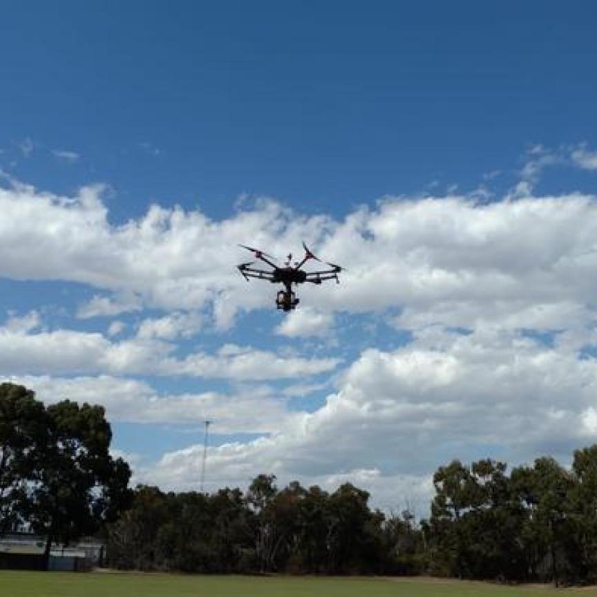
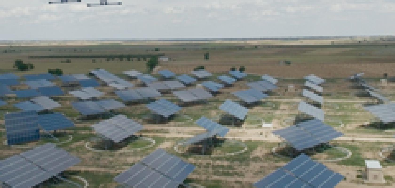
In the past two years, Enertis has begun performing aerial inspections using drone technology. By attaching a thermal camera to a drone, technicians can achieve a bird’s-eye view of a PV plant, allowing it to sweep a wider area, cover more solar cells, and detect thermal anomalies on a much larger scale than ground-based methods. This enhanced field of vision dramatically reduces the time it takes to carry out an inspection of a PV plant. ‘The work that you can do in two weeks with two people walking around a whole plant – for the same area of inspection, and getting just the image of that area – a drone can do in very few days, depending on the inspection requirements,’ said Velasco. ‘The drone drastically reduces the time you have to spend on site, which is normally the most expensive part.’ For PV plant owners and operators, this is rapidly becoming the preferred method of carrying out a site evaluation.
Thermal imaging cameras must first be adapted before they can be attached to an aerial drone. ‘Cameras used for drones differ from those used for ground inspections mostly through physical attributes,’ explained Velasco. They have to be smaller to avoid affecting the drone’s flight or power consumption. This can be achieved without having to make compromises to the camera’s thermal imaging technology. ‘For ground inspections, manufacturers design cameras to be more ergonomic; they are handheld, sometimes like pistols, making them comfortable to use,’ continued Velasco. Because of the extended periods of time that cameras are used during a ground inspection, this is an essential quality. However, for aerial inspections, manufacturers are able to remove these superfluous ergonomic features, while conserving the optics and internal thermal hardware. ‘In terms of thermal specifications, drone cameras will be similar to ground inspection cameras,’ said Velasco.
Few manufacturers offer suitable cameras for mounting underneath aerial drones, as aerial thermal inspection is still a relatively new technique. Several aspects of Panoptes’ mT-Panoptes inspection system make it an ideal candidate for mounting underneath a drone – it is small (76 x 52 x 60mm) and lightweight (≤600g). The system includes Flir’s Tau core, which enables the camera to produce crisp thermal images with a resolution of 640 x 512 pixels. According to Velasco, this is what the top of the range cameras will show.
Despite having comparable resolutions, basic physics means the detail of an image captured by a drone-mounted camera can never be as high as that of a ground-based camera. From further away, each available pixel covers a larger area, reducing the camera’s ability to capture the detail. This is not an issue for QA companies such as Enertis, as drone inspections are not intended to achieve the same goals as a thorough ground inspection. ‘Normally the drone is used to perform a quick scan of the whole area to identify where the hotspots are – not so much for stopping at a single defect to analyse what it is,’ said Velasco. ‘With aerial inspections you tend to cover the whole area and then analyse the images once you are finished.’ Drones allow technicians to map all the thermal anomalies around a solar plant in a short period of time. A ground team can then go and analyse each problem individually.
In the long-wave infrared band, glass has an emissivity of 0.85-0.90 (1.0 being the highest value possible), making it very effective at emitting the absorbed thermal energy generated by faults or defects. Despite this, the specular reflective properties of glass can generate false thermal readings by reflecting the infrared radiation of objects surrounding a solar panel, such as the operator of the camera, or the camera itself. This can lead to false hot spots appearing in a thermal image. Emissivity is greatest when a camera is positioned perpendicularly to a panel; however, at this angle, the camera will be reflected clearly in the glass. Increasing the viewing angle will avoid this, but the level of emissivity will reduce as a result. According to Flir, observing a solar panel at an angle around 60° offers the optimal compromise between the level of reflection and emissivity. Setting the flight path of a drone before an inspection allows technicians to control the angle of observation and other factors throughout the flight. ‘One thing we do is an engineering plan,’ said Velasco. ‘We plan the height and speed of the flight beforehand. The flight is designed to enable us to pick up all the types of defect we can search for.’ In this way, the technicians optimise their time on site.
Drone-assisted thermal inspection is still developing. ‘It’s just a matter of time before this becomes the standard in the service,’ said Velasco. ‘There are a lot of tests to be done and we will be learning as we go, but every day we learn new tricks and how things can be better in terms of height, angles, equipment, speeds, and flight plans.’
Thermal imaging is just one option in a range of methods for inspecting solar cells with infrared imaging. Electroluminescence and photoluminescence are both widely used to characterise faults and defects in solar cells using cooled CCD or infrared cameras.
Both Xenics and Allied Vision offer shortwave infrared InGaAs cameras for luminescence inspection. Electroluminescence is the emission of light resulting from a forward bias voltage applied to a solar cell. The electrons injected into the solar cell recombine with the existing holes, while the energy released by this process is given off to a small extent in the form of a photon. These emitted photons have wavelengths in the near and shortwave infrared, detection of which by infrared cameras gives a measure of the uniformity of the solar cell. Electroluminescence imaging can be used for detecting cracks, grain boundaries, broken contacts and shunts in a solar cell. It also enables the series resistances of a cell to be mapped, in addition to indicating cell material quality.
Photoluminescence works on principals similar to electroluminescence. Optical excitation, such as from laser illumination, is used to generate electron-hole pairs, which cause emissions by radiative recombination that are detectable by an infrared camera.
‘InGaAs cameras are especially advantageous in the capture of photoluminescence images since their quantum efficiency in the shortwave infrared is rather high,’ said Raf Vandersmissen, CEO of InfraRed and product manager at Xenics.
According to Allied Vision, the band-to-band emission around 1,150nm produces information on defects and dislocation clusters. Mapping the luminescence resulting from defects at around 1,550nm provides information on the limit of the cell’s efficiency.