Some technologies (the IT industry is an obvious example) develop so rapidly that it is difficult to keep track of the recent innovations – with seemingly revolutionary upgrades in the pipeline before most companies have had a chance to install the previous offerings. But, often, a manufacturer’s rush to reach the next milestone in performance can take its toll on the robustness of the devices.
Other technologies may be more sluggish in their developments, but like the tortoise in Aesop’s fable of the tortoise and the hare, their strength lies in a slow but steady progress that ultimately produces a greater reliability. If recent talks at the Vision Show in Boston, Massachusetts this June, and IPOT/MV event in Birmingham, UK, last February are anything to go by, 3D vision technology has benefited from this slow road to fruition, with steady improvements in accuracy, reliability and speed that have ultimately produced a higher-quality product.
Over the years, a multitude of different techniques to capture still 3D data have evolved (and that’s not to mention 3D motion capture – see panel). Depending on data required, 3D images can be achieved with either just one camera, or two or more cameras, but the usefulness of each technique does depend on the job in hand.
Many 3D vision techniques rely on simple mathematics to infer the distance of objects. For example, the further away the object is, the smaller it will appear in the image, and it’s possible to calculate the distance of objects simply by analysing the size of their features (for example, the drill hole of a mechanical component).
This method can also be used to measure the orientation of the object. When viewed in a 2D image, objects appear to change shape when tilted (for example, a circle will become an ellipse) and by comparing the ratio of the dimensions of the object as it appears on the image, software can calculate angular coordinates of the object’s orientation.
This method does have its limitations – it can’t produce a detailed 3D profile of objects for inspection applications, and it requires detailed prior knowledge of the objects – but it can be used to guide robots designed to pick up and move components on the factory floor.
Like many one-camera methods, this technique requires a careful calibration of all the internal features of the camera, such as the focal length, radial distortion coefficient and the sensor pixel pitch. This ensures that all potential factors that could influence the results have been taken into account before the software analyses the images, to produce the most accurate data.
Some systems employ a 3D matching technique, in which the 2D image is compared to a 3D CAD model of the object. The software can calculate at what rotation and distance the CAD model would need to be to reproduce the 2D captured image, and from this produces suitable coordinates of its position.

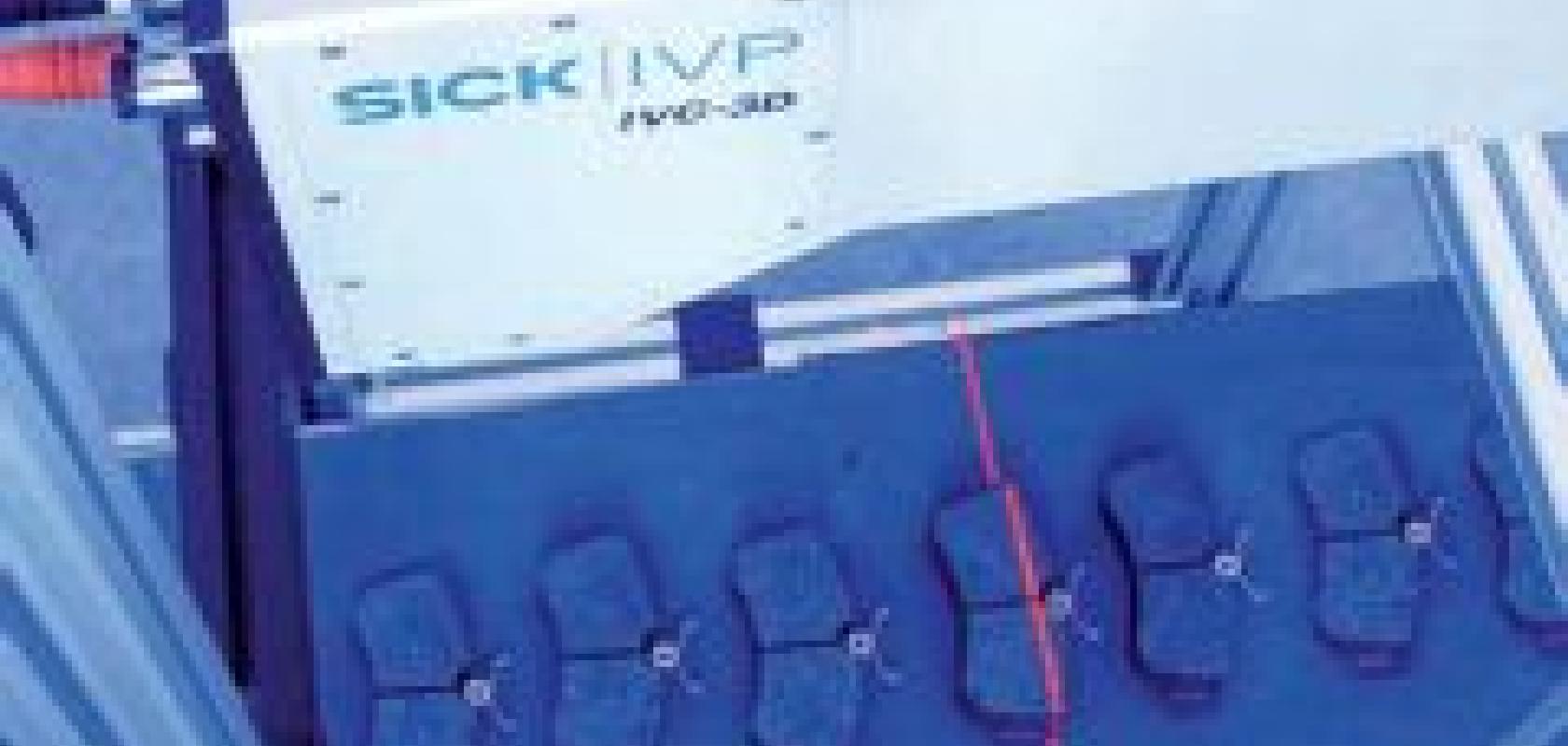
A Sick system uses laser triangulation to build a 3D profile (below) of brake pads on a conveyor belt.
‘It’s basically template-matching,’ says Heiko Eisele, the president of MVTec, who gave a presentation on applying standard cameras to 3D vision at the Vision Show. ‘By knowing the entire imaging geometry the system forms a reconstruction of the image from the CAD model.’ This technique would also be used for bin picking applications on the factory floor.
One of the more sophisticated one-camera techniques is the depth-from-focus method. This technique relies on the fact that for each setting of the lens, only features at a certain depth will be in focus. Systems that make use of this method successively alter the focus of the lens, taking images at each step. By analysing which pixels are in focus and which are blurred in an image, software can calculate the depth of each feature of the object to build a 3D profile.
3D profiles of objects would be used for quality control applications, rather than robotics applications. 3D information is often useful to ensure that products are of the correct size, and it can also be used to detect defects (such as chips or scratches in a surface, or knots in wood) that may not be obvious in 2D images.
A very common 3D measurement technique in this vein is the time-of-flight method. These systems scan a laser beam across the object’s surface. The beam reflects from each point on the object and returns to the system to be recorded by an image sensor. By precisely measuring the length of time that it takes for the laser beam to travel and return to the sensor, the system can calculate the distance of the object at that point.
By scanning the laser across the whole object and making measurements in this way, it can very quickly build up a detailed profile of the 3D shape of the object. ‘It’s very simple and straightforward – it works well outdoors, and by altering the wave properties of the laser, it’s possible to achieve a good resolution,’ says Karl Gunnarsson, the vision business development manager at Sick IVP.
Another popular method to produce a 3D profile is the laser triangulation method. This technique also uses a laser and a camera. In this case, the laser, positioned at an angle to the camera, projects a line of light that falls across the object. Viewed from the camera’s angle, the line of light follows the contours of the object, highlighting its cross-section at this point. The camera would then record this shape. By recording the cross-section of the object at successive points in this manner, the system then compiles the 3D profile of the object. This method is particularly useful when installed above a conveyor belt, which carries the object through the line of laser light while the camera records the cross-section at regular time intervals.
‘A typical application would be the inspection of wood at the saw mill,’ says Gunnarsson. ‘The board passes through the laser light at a high speed, and the camera records the 3D image.
‘Laser triangulation has a better resolution than time of flight measurement – you can achieve resolutions as low as a few microns.’ However, this method can’t work in ambient light, so it can only work indoors, whereas time-of-flight measurement is also suitable for outdoor applications.
The laser triangulation method uses the same geometric principle (triangulation) as the most common two-camera method – stereovision, which uses two cameras to view the same object from different angles. ‘Based on the geometry, both images will be slightly different. Our software can calculate the disparity of the images for each pixel, and use this information to calculate the distance,’ explains MVTec’s Eisele.


The depth-from-focus technique builds a 3D profile of an object by alternately adjusting the lens setting of a camera. Features of different depth will appear in or out of focus at each frame. Image courtesy of MVTec.
Advances in technology
According to Sick’s Gunnarsson, one of the biggest developments in 3D vision technology is a vast improvement in the speed at which the data can be collected – particularly for the laser triangulation technique. ‘Using CMOS sensors we can deliver 35,000 frames per second, with a separate 3D profile for each frame,’ he says.
Unlike CCD sensors, CMOS sensors have the advantage that most of the digitalisation and processing of the image can be done directly on the image sensing chip.
In addition, the sensors can also pick up greyscale images, as well as the 3D information – allowing the companies to integrate the different types of inspection required for an application within one system. ‘It can describe the height, to figure out 3D surface features, and the greyscale information about the shading on its surface,’ says Gunnarsson.
This would be useful in fruit inspection, for example. The 3D information could pick out worm holes within the surface, and the greyscale information would highlight bruises on the skin.
This integration of 3D inspection in different types of machine vision seems to be a growing trend within the vision industry. Gunnarsson explains that Sick has recently borrowed optical character recognition technology from 2D inspection for use with 3D vision. This is suitable for applications where a code is engraved into metal components. In heavy industrial situations, printed bar codes would soon be rubbed off, but engraved codes are a more robust method of identifying parts.
‘The OCR algorithms stay exactly the same [as with 2D recognition],’ he says. ‘The way we represent the image, the higher the feature is, the brighter it is, so we can use the same tools to isolate the different letters.’
MVTec’s Eisele agrees that the integration of different technologies is very important for inspection applications. MVTec’s machine vision software library, Halcon, makes this possible by providing the different software components for the different applications in one package.
Ease of use is another important goal that companies are striving towards. Sick is achieving this by providing the different components – the software, the camera and the laser – in one package, to make it easy to program for any application. ‘It’s drag and drop technology – it shouldn’t take a PhD to use,’ says Gunnarsson.
Unsurprisingly, given the technology’s slow but steady progress, manufacturers are still constantly working on making the technology as reliable as possible. MVTec is concentrating on producing a more robust 3D matching technology that can more accurately identify objects from their CAD files, and to improve the camera calibration required for the many different techniques.
In addition, manufacturers are always looking for new techniques in 3D vision, developed in academic research, that could be applied for industrial applications. ‘But we have to do our own research to make these techniques useful [in an industrial setting],’ says Eisele.
It’s possible that this research could revolutionise the way 3D vision is performed on the factory floor but, given the history of the technology, it seems more likely to result in more steady improvements that provide more precise, more accurate, reliable and faster 3D measurements.
In some instances, it’s not enough to simply record information about the shape of an object in 3D – it’s also necessary to understand how it moves in a 3D environment. The film industry often uses 3D motion capture to animate characters (the recent Beowulf film relied heavily on these techniques) and it’s also used heavily in medicine to analyse patients’ gait and posture.
Previously, 3D motion capture relied on highly visible, shiny white ‘markers’ attached to the subjects joints. An array of many cameras surrounding the subject would capture its movement from every angle, and vision processing software would tag and track each marker, following its movement to try to reconstruct how they were moving.
If the subject is a person, he would normally have to wear tight black clothing, to make the markers more noticeable to the processing software.
‘It’s not a natural way to dress, and can affect how they behave,’ says Christian Theobalt from Stanford University in the US. Despite this precaution, the software was still easily confused by the moving markers, and often required hours of post processing to correct mistakes.
For some time, researchers have been looking for ways to get around this by eliminating the need for markers altogether. Previous markerless techniques often lacked accuracy, but Theobalt believes he has found a way past these limitations.
Theobalt’s system first laser scans the subject to build a 3D model of its starting position. Eight cameras, surrounding the subject at different angles, then track its motion throughout the scene. In each frame in the film, software blacks out the background to create a silhouette of the subject.
By comparing differences in the eight silhouettes taken from the different angles, the software then calculates how the initial 3D model must be adapted to fit these images. When performed successively on each frame, the system can build a detailed 3D animation that exactly replicates the motion.
As a finishing touch, it uses stereo vision (see main article) to capture fine details, such as the ruffles within the actor’s clothing. Unlike marker-based techniques, the actors could dress up in suitable costumes, and it can even capture the motion of long flowing dresses.
‘Some sequences we’ve filmed would have been too hard to film with markers,’ says Theobalt, who will present his work at the Siggraph 2008 conference in Los Angeles this August.