Paul Wilson, managing director of Scorpion Vision, describes what it takes to install a 3D robot vision system in a Chinese foundry
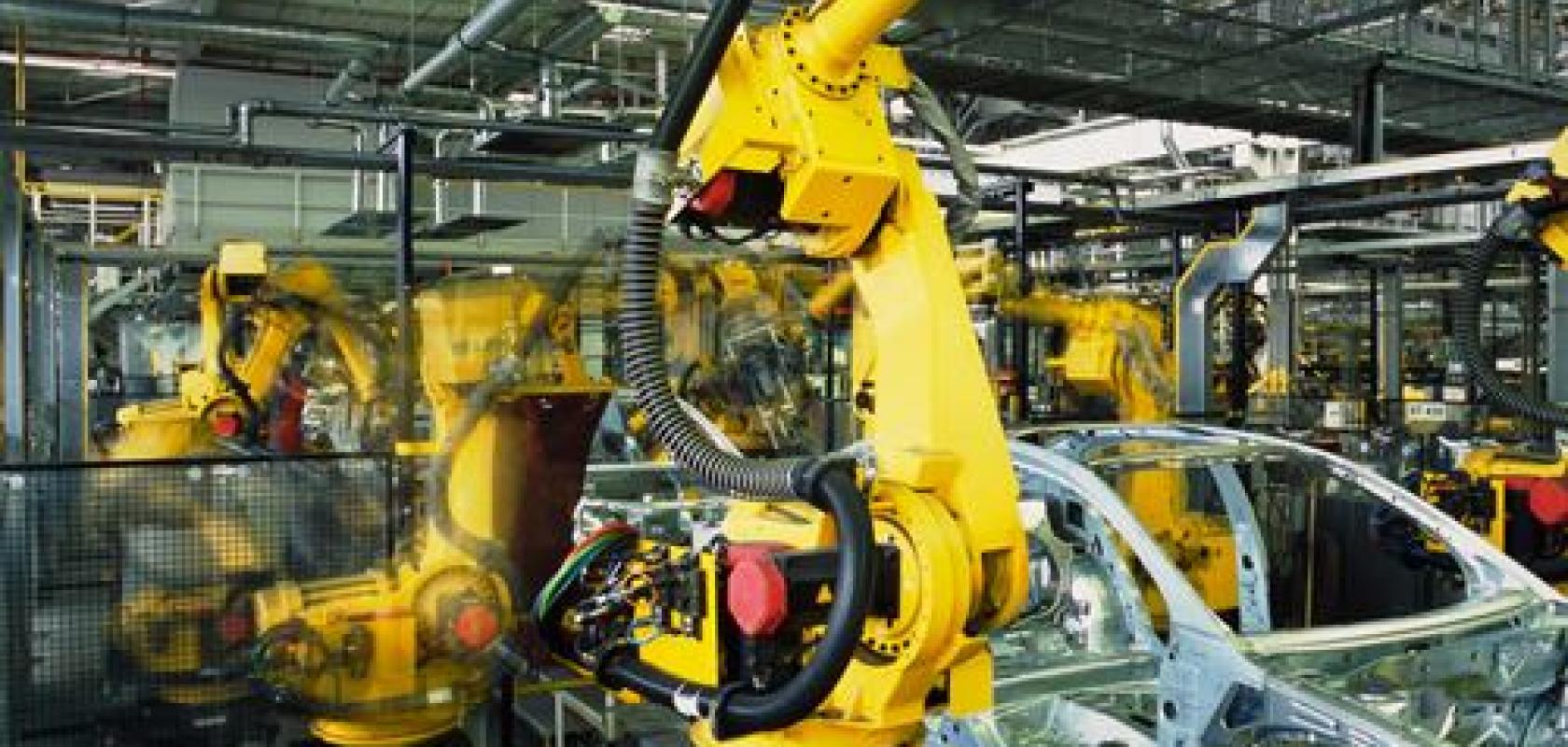
In 2017, Scorpion Vision entered into a partnership with a Chinese automation firm that specialises in delivering robotic systems to foundries. The two companies worked together to deliver a 3D robot vision system able to handle automotive casted parts such as engine blocks and cylinder heads. The Scorpion 3D Stinger camera system was integrated with the automation company’s robot cells.
The most common requirement from the end-customer was for the robot to identify casted parts. In most cases, the parts are removed from the cast and placed on a conveyor before being picked by a robot.
In the case of the engine blocks, these are picked by a large six-axis robot and moved to a deburring machine before being placed back onto the conveyor. The 3D vision system solved the problem of how to locate the engine block if it is not sitting flat and straight. Several features had to be located using 3D vision and with 0.5mm accuracy in the z axis. Once this was achieved, the robot could pick up the engine block regardless of the angle or position, 100 per cent of the time.
The vision system architecture is based on stereo vision with random pattern projection. Internally, the Scorpion 3D Stinger camera contains a synchronisation board that controls the application of the light source at the right moment. This is usually a combination of both infrared LED and infrared laser, synchronised with the right amount of power for the application, which is ultimately controlled by the vision software. So, the LED strobe, when the laser fires, and the power levels are all managed to get the optimum image in what can be a harsh environment for machine vision.
Images can be acquired with the laser in one set and the LED in another before they are processed together to get both 2D area scan images and 3D height maps and models. Any deficiency of the optical system will be highlighted here as a robust and repeatable 3D model is critical.
Operating in the near infrared frequency range means the system is less susceptible to changing ambient light than it would be if the light source was in the visible range. Although this can’t protect completely against strong sunlight or extreme variations of light, it does mean there is a robustness which is easily achieved using NIR sensors with 850nm bandpass filters.
The work to specify the camera design started in the UK with standard parameters being recorded – ambient light, operating distance, product dimensions, number of variants, etc. The details were then passed to Tordivel in Oslo, which is the company behind the camera technology. The camera was built with the optical components that match the parameters of the application, tested and calibrated before being despatched to Scorpion Vision in the UK where it was tested again and a final 3D calibration was applied before despatch to China.
The Chinese integrator had already received training with the vision software, so when the camera arrived, the engineers’ first job was to build up the system and, when everything was ready, take the first set of images. The team at Scorpion Vision worked with the Chinese integrators using a remote access connection and therefore worked directly on the PC in the Chinese factory.
The process
Images were collected and saved to a remote archive where the team in the UK built the application. In the meantime, the integrator created the interface to the robot system and verified that everything is connected and working.
When the machine vision picking application was ready, it was uploaded to the remote machine and tested with live images at the site. If initial results were good, product variants were then presented to the system for image collection. The next stage was to add the new variant images to the application and, once done, these were tested thoroughly at the site.
The UK- and Chinese-based engineers worked together to prove the system, evaluating, testing and stressing the system before it was signed off by the customer.
The final stage before the factory acceptance test was probably the longest process as there were inevitable challenges to overcome.
The top five challenges present in every project are:
- Teams working together from two different time zones;
- Cultural and language difficulties, often relying on online translators to get the message across;
- Managing two different sets of expectations for each phase of the project;
- The inevitable ambient lighting issue when we don’t have full control of the environment;
- Parts to be picked don’t conform to the minimum standard in order for the vision system to work reliably.
The biggest challenge for the project, which increases the risk, was the time to complete. All the above highlighted points result in an accumulation of time and this was possibly the biggest threat to getting a successful outcome.
Write for us
Let us know about a successful vision installation and what it took to deploy it. Email: greg.blackman@europascience.com.